background image

1-5  Installing an Expansion Card

Read the following guidelines before you begin to install an expansion card:


Make sure the motherboard supports the expansion card. Carefully read the manual that came 

with your expansion card.


Always turn off the computer and unplug the power cord from the power outlet before installing an 

expansion card to prevent hardware damage.

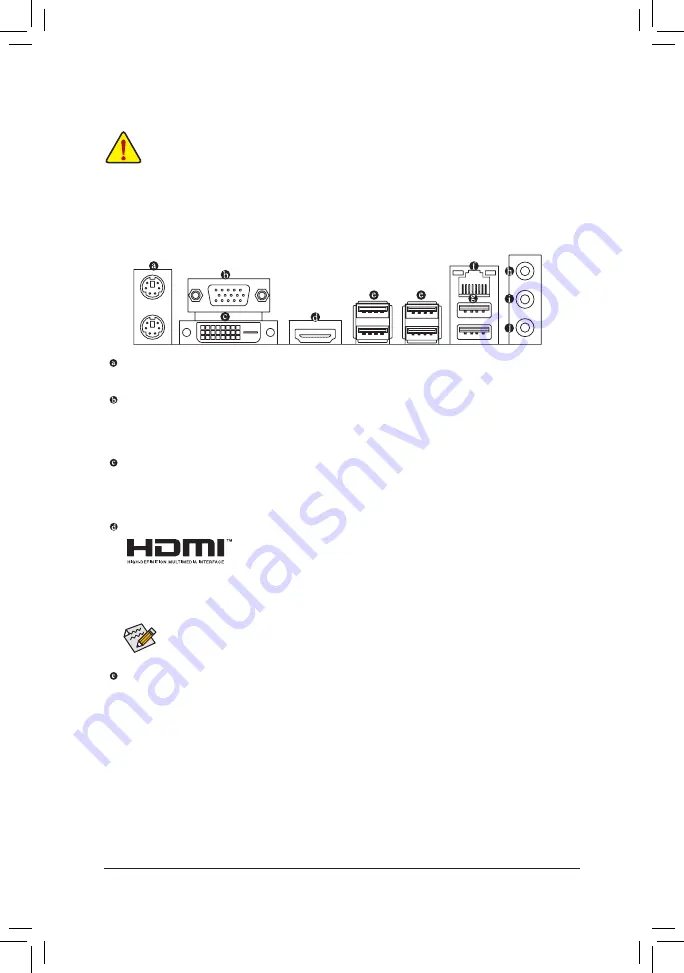
1-6  Back Panel Connectors

PS/2 Keyboard and PS/2 Mouse Port

Use the upper port (green) to connect a PS/2 mouse and the lower port (purple) to connect a PS/2 keyboard.

D-Sub Port

The D-Sub port supports a 15-pin D-Sub connector and supports a maximum resolution of 1920x1200@60 Hz 

(the actual resolutions supported depend on the monitor being used). Connect a monitor that supports 

D-Sub connection to this port.

DVI-D Port 

(Note 1)

The DVI-D port conforms to the DVI-D specification and supports a maximum resolution of 1920x1200@60 Hz 

(the actual resolutions supported depend on the monitor being used). Connect a monitor that supports 

DVI-D connection to this port.

HDMI Port

The HDMI port supports HDCP 2.2 

(Note 2)

 and Dolby TrueHD and DTS HD 

Master Audio formats. It also supports up to 192 KHz/16bit 8-channel LPCM 

audio output. You can use this port to connect your HDMI-supported monitor. The maximum supported 

resolution is 4096x2160@60 Hz 

(Note 2)

, but the actual resolutions supported are dependent on the 

monitor being used.

After installing the HDMI device, make sure to set the default sound playback device to HDMI. (The 

item name may differ depending on your operating system.)

USB 3.1 Gen 1 Port

The USB 3.1 Gen 1 port supports the USB 3.1 Gen 1 specification and is compatible to the USB 2.0 

specification. Use this port for USB devices.

(Note 1)  The DVI-D port does not support D-Sub connection by adapter.

(Note 2)  Actual support may vary by CPU.

- 10 -

Summary of Contents for B450M S2H

Page 1: ...global warming the packaging materials of this product are recyclable and reusable GIGABYTE works with you to protect the environment For more product details please visit GIGABYTE s website B450M S2...

Page 2: ...d transmitted or published in any form or by any means without GIGABYTE s prior written permission In order to assist in the use of this product carefully read the User s Manual For product related in...

Page 3: ...Memory 9 1 5 Installing an Expansion Card 10 1 6 Back Panel Connectors 10 1 7 Internal Connectors 12 Chapter 2 BIOS Setup 20 2 1 Startup Screen 20 2 2 The Main Menu 21 2 3 M I T 22 2 4 System 26 2 5 B...

Page 4: ...450M S2H motherboard 5 5 Two SATA cables 5 5 Motherboard driver disk 5 5 I O Shield 5 5 User s Manual KB_MS CPU_FAN SYS_FAN1 LED_CPU ATX B450M S2H AUDIO DDR4_2 DDR4_1 BAT ATX_12V AMD B450 R_USB30_1 HD...

Page 5: ...metal object to eliminate static electricity Prior to installing the motherboard please have it on top of an antistatic pad or within an electrostatic shielding container Before connecting or unplugg...

Page 6: ...ing a maximum resolution of 4096x2160 60 Hz Note 1 Support for HDMI 2 0 version and HDCP 2 2 Note 1 Maximum shared memory of 2 GB Audio Realtek ALC887 codec High Definition Audio 2 4 5 1 7 1 channel T...

Page 7: ...e only 1 x speaker header 1 x Clear CMOS jumper 1 x chassis intrusion header Back Panel Connectors 1 x PS 2 keyboard port 1 x PS 2 mouse port 1 x D Sub port 1 x DVI D port 1 x HDMI port 4 x USB 3 1 Ge...

Page 8: ...Blocker Support for Q Flash Support for Xpress Install Bundled Software Norton Internet Security OEM version Realtek 8118 Gaming LAN Bandwidth Control Utility Operating System Support for Windows 10...

Page 9: ...lling the Memory Dual Channel Memory Configuration This motherboard provides two memory sockets and supports Dual Channel Technology After the memory is installed the BIOS will automatically detect th...

Page 10: ...t conforms to the DVI D specification and supports a maximum resolution of 1920x1200 60 Hz the actual resolutions supported depend on the monitor being used Connect a monitor that supports DVI D conne...

Page 11: ...nel 7 1 channel Line In Rear Speaker Out a a a Line Out Front Speaker Out a a a a Mic In Center Subwoofer Speaker Out a a Front Panel Line Out Side Speaker Out a Please visit GIGABYTE s website for de...

Page 12: ...Unplug the power cord from the power outlet to prevent damage to the devices After installing the device and before turning on the computer make sure the device cable has been securely attached to the...

Page 13: ...not start To meet expansion requirements it is recommended that a power supply that can withstand high power consumption be used 500W or greater If a power supply is used that does not provide the re...

Page 14: ...system may hang These fan headers are not configuration jumper blocks Do not place a jumper cap on the headers 3 4 CPU_FAN SYS_FAN1 Fan Headers All fan headers on this motherboard are 4 pin Most fan h...

Page 15: ...B_ B _ S S_ _ B _ U _ B S S U 1 2 3 _ _ 3 F_USB3 F F _ 0 S S 80 60 42 7 SPDIF_O S PDIF Out Header This header supports digital S PDIF Out and connects a S PDIF digital audio cable provided by expansi...

Page 16: ...ff your system using the power switch refer to Chapter 2 BIOS Setup Power for more information HD Hard Drive Activity LED Connects to the hard drive activity LED on the chassis front panel The LED is...

Page 17: ...ingle short beep will be heard if no problem is detected at system startup Pin No Definition 1 VCC 2 NC 3 NC 4 SPK 1 Prior to installing the USB front panel be sure to turn off your computer and unplu...

Page 18: ...requires a chassis with chassis intrusion detection design 1 Pin No Definition 1 Signal 2 GND 15 CLR_CMOS Clear CMOS Jumper Use this jumper to clear the BIOS configuration and reset the CMOS values t...

Page 19: ...with an equivalent one Damage to your devices may occur if the battery is replaced with an incorrect model Contact the place of purchase or local dealer if you are not able to replace the battery by...

Page 20: ...te BIOS flashing may result in system malfunction It is recommended that you not alter the default settings unless you need to to prevent system instability or other unexpected results Inadequately al...

Page 21: ...the previous BIOS settings for the current submenus F7 Load the Optimized BIOS default settings for the current submenus F8 Access the Q Flash utility F9 Display system information F10 Save all the ch...

Page 22: ...to alter the frequency for the GPU After you alter the GFX Clock Frequency settings make sure to adjust the GFX Core Voltage settings Default Auto NOTE The adjustable range is dependent on the CPU be...

Page 23: ...states When enabled the CPU core frequency will be reduced during system halt state to decrease power consumption Default Enabled Power Supply Idle Control Enables or disables Package C6 State Typical...

Page 24: ...he BIOS automatically configure this setting Default Auto Channel A B Memory Sub Timings This sub menu provides memory timing settings for each channel of memory The respective timing setting screens...

Page 25: ...an to run at full speeds Fan Control Use Temperature Input Allows you to select the reference temperature for fan speed control Temperature Interval Allows you to select the temperature interval for f...

Page 26: ...Page Up or Page Down key to set the desired value System Time Sets the system time The time format is hour minute and second For example 1 p m is 13 00 00 Use Enter to switch between the Hour Minute a...

Page 27: ...ort Boot from LAN function etc Press Enter on this item to enter the submenu that presents the devices of the same type that are connected This item is present only if at least one device for this typ...

Page 28: ...is set to Ultra Fast PS2 Devices Support Disabled All PS 2 devices are disabled before the OS boot process completes Enabled All PS 2 devices are functional in the operating system and during the POS...

Page 29: ...Stack is enabled Administrator Password Allows you to configure an administrator password Press Enter on this item type the password and then press Enter You will be requested to confirm the password...

Page 30: ...operating system without XHCI Hand off support Default Enabled EHCI Hand off Determines whether to enable EHCI Hand off feature for an operating system without EHCI Hand off support Default Disabled P...

Page 31: ...r system supports 64 bit PCI decoding Set to Enabled if more than one advanced graphics card are installed and their drivers are not able to be launched when entering the operating system because of t...

Page 32: ...e this setting Default UMA Specified Sets the UMA Frame Buffer Size UMAAuto Sets the display resolution This item is configurable only when Integrated Graphics is set to Forces UMA Frame Buffer Size N...

Page 33: ...plug Default NVMe RAID mode M2A_SOCKET Connector Allows you to determine whether to use your M 2 NVMe PCIe SSDs to configure RAID Default Disabled APU SATA Port Enable M2A_SOCKET Connector Enables or...

Page 34: ...n the Windows 98 keyboard to turn on the system Any key Press any key to turn on the system Power On Password Set the password when Power On By Keyboard is set to Password Press Enter on this item and...

Page 35: ...Enabled Auto lets the BIOS automatically configure this setting Default Auto Resume by Alarm Determines whether to power on the system at a desired time Default Disabled If enabled set the date and t...

Page 36: ...he device you select and select Yes to confirm Your system will restart automatically and boot from that device Save Profiles This function allows you to save the current BIOS settings to a profile Yo...

Page 37: ...the legacy RAID ROM save the settings and exit BIOS Setup Refer to C 2 for more information The BIOS Setup menus described in this section may differ from the exact settings for your motherboard The...

Page 38: ...ating System With the correct BIOS settings you are ready to install the operating system Installing the Operating System As some operating systems already include Intel RAID AHCI driver you do not ne...

Page 39: ...ner of the screen and select Run Run exe Or go to My Computer double click the optical drive and execute the Run exe program 3 2 Drivers Installation Xpress Install will automatically scan your system...

Page 40: ...posed of properly WEEE Symbol Statement The symbol shown below is on the product or on its packaging which indicates that this product must not be disposed of with other waste Instead the device shoul...

Page 41: ...of the following measures Reorient or relocate the receiving antenna Increase the separation between the equipment and receiver Connect the equipment into an outlet on a circuit different from that to...

Page 42: ...912 4000 FAX 886 2 8912 4005 Tech and Non Tech Support Sales Marketing https esupport gigabyte com WEB address English https www gigabyte com WEB address Chinese https www gigabyte com tw GIGABYTE eSu...

Reviews: