background image

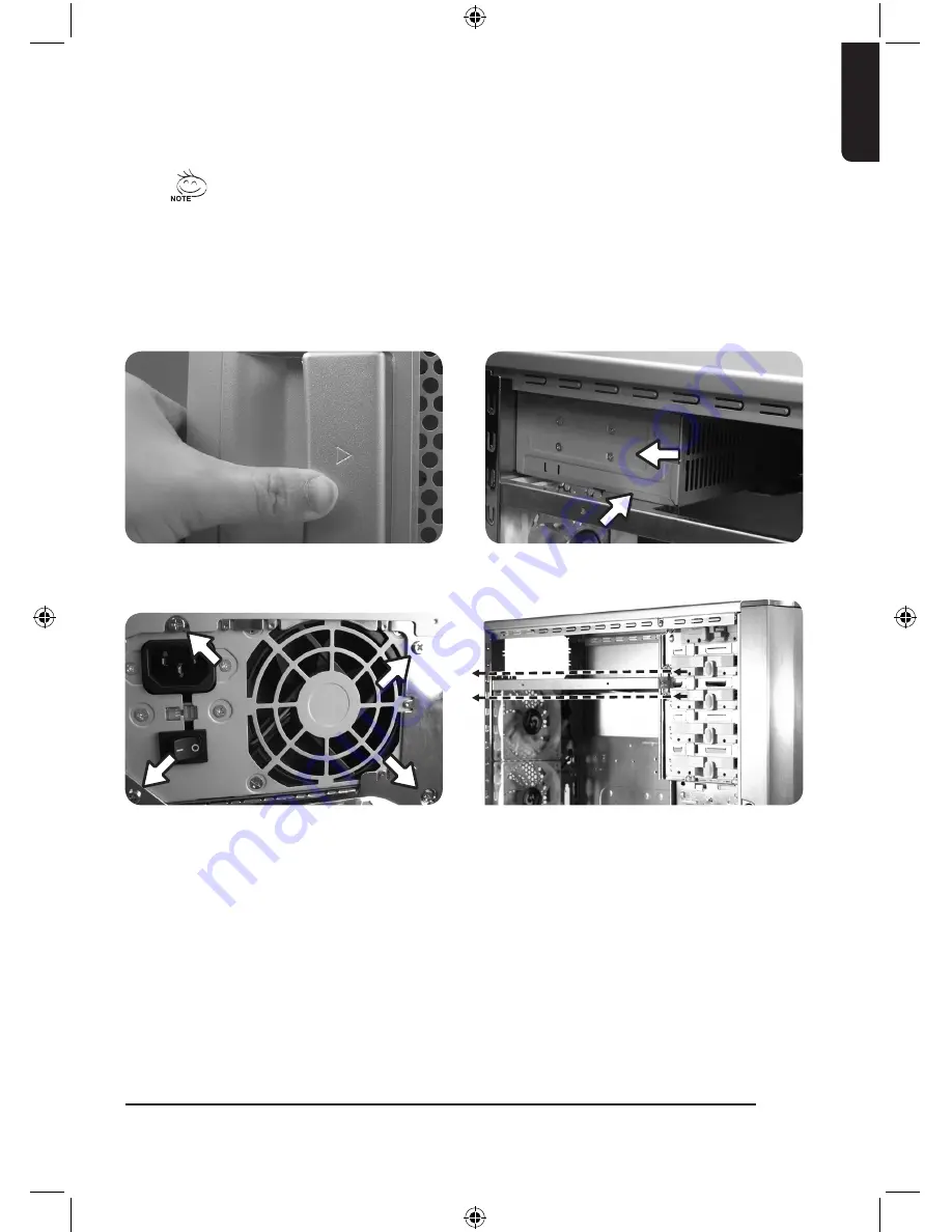
4-1 Installation of Power Supply

To facilitate the installation, it is recommended to set the chassis upright on
the table.

Required parts: power supply securing screws x 4

4. Installation Instruction

Please follow the reference sections in order for installation

4-2 Installation of Motherboard

3DAURORA / 3DAURORA 570S is compatible with the ATX/Micro ATX/Flex ATX 
motherboards. 
3DAURORA 570 is compatible with the ATX/Micro ATX/Flex ATX/CEB/E-ATX 
motherboards. 
Please confirm the dimension and fixing points of the motherboard before
installation
Required parts: Copper stand offs, securing screws

4-1-1  Unscrew the thumbscrews of the side panel 

and detach the panel by press the latch to 

remove the side panel.

4-1-2  Place the power supply unit into the case

4-1-3  Secure the power supply unit with screws from 

the rear of chassis

4-1-4  When using large power supply unit, please 

disassemble the cross bar by loosing screws. 

Fasten the screws to secure the cross bar 

after the power supply installed.

En

glis

h

09

Summary of Contents for 3DAURORA

Page 1: ...GZ FSCA1 ANS ANB ATS ATB 3DAURORA GZ FA1CA ASS ASB 570 GZ FA1CB AJS AJB 570S English User s Manual 3DAURORA Series 3DAURORA 3DAURORA570 3DAURORA570S ...

Page 2: ...ce from other devices 4 Unapproved modification of the product 5 Consequential damage to other objects due to the product s fault 6 Malfunction arising from natural hazards e g earthquake lightning fire and floods 7 The product s warranty label has been removed or damaged 8 The devices inside including power supply hard disk CD ROM drive mother board ventilator etc are not detached from the casing...

Page 3: ... card 10 4 4 Installation of Front Multi Media I O Ports 11 4 5 Connection of Cooling Fan power lines 12 4 6 Installation of 5 25 Front Drive Bay 13 4 7 Installation of 3 5 Front Device Bay 13 4 8 Installation of 3 5 Internal Device Bay 14 4 9 Application of DIY Projector Bracket 14 4 10 Application of Security locks 15 4 11 Application of Foot Supports 15 4 12 Application of Liquid Cooling System...

Page 4: ...1 Components Introduction 1 1 Casing s Internal Structure 1 3 2 9 4 5 6 8 7 PCI Tool Free Fastener 5 25 Front Device Bay Motherboard tray and PCI Slot panel Power Supply Bay 1 2 3 4 English 04 ...

Page 5: ...AURORA at tached on front panel a 3DAURORA 570S Copper Stand Offx9 570 Copper Stand Offx12 b Power Extension Cablex2 c Securing Runnerx10 d Key x 2 e Wire clamp x 2 f 3DAURORA 570S Moth erboard Securing Screw x 9 570 Motherboard Securing Screw x 12 g Power Supply Securing screw x 4 g Projector LED 4 pin Connector a USB 2 0 b Audio HD AC97 c IEEE1394 Multi connectors d Fan 3 Pin Connector e Power L...

Page 6: ...ed Mesh GZ FSCA1 ANS ANB Transparent Side Panel GZ FSCA1 ATS ATB 3DAURORA c 1 Front Panel c 2 Security Lock c 3 Power Reset Switches Front Multi Media I O port c 4 Projector b 2 Piping Out lets B Rear Panel b 1 Dual Rear fans 3DAURORA 570 3DAURORA 570S c 1 Front Panel c 2 Security Lock c 3 Power Reset Switches Front Multi Media I O port c 4 Projector C Front Panel English 06 ...

Page 7: ...tion LCS and Air cooling products lines Support ATX Micro ATX Flex ATX motherboard 3DAURORA 3DAURORA 570S Support ATX Micro ATX Flex ATX CEB E ATX motherboard 3DAURORA 570 Integration of Cooling Technology Aluminum alloy chassis for accelerating system cooling performance Industry leading dual rear 12cm silent blue LED fan large air volume with low noise Unique ventilated mesh transparent side pan...

Page 8: ...kel plated SECC 1 0mm Net weight 8 5 KG 5 25 drive bay external 5 3 5 drive bay external 2 3 5 drive bay internal 5 PCI slot 7 Motherboard size ATX Micro ATX Flex ATX System Fan Front 1 x 12cm Silent Blue LED fan 1000 RPM System Fan Rear 2 x 12cm Silent Blue LED fan 1000 RPM Multi Media I O port 2 x USB 2 0 1 x IEEE1394 1 x audio jacks HD AC97 570S Specification Model GZ FSCA1 ANS ANB ATS ATB Case...

Page 9: ... with the ATX Micro ATX Flex ATX CEB E ATX motherboards Please confirm the dimension and fixing points of the motherboard before installation Required parts Copper stand offs securing screws 4 1 1 Unscrew the thumbscrews of the side panel and detach the panel by press the latch to remove the side panel 4 1 2 Place the power supply unit into the case 4 1 3 Secure the power supply unit with screws f...

Page 10: ...ing points of the motherboard tray 4 2 2 Change the motherboard I O bracket at the rear of the slot panel typically supplied by motherboard manufactures 4 3 4 Lock the PCI slot retention lock to secure 4 3 1 Unlock the PCI slot re tention lock 4 3 2 Remove the internally attached dust proof PCI slot 4 3 3 Insert the add on card into the ex pansion slot with care Motherboard Code on tray Securing s...

Page 11: ...ns provided by the motherboard manufacturer 4 4 Installation of Front Multi Media I O Ports Pin Definition Pin Definition 1 Power 6 USB Dy 2 Power 7 GND 3 USB Dx 8 GND 4 USB Dy 9 5 USB Dx 10 USB Over current USB 2 0 connector 4 4 2 Insert the IEEE 1394 connector into the corresponding socket on the mother board There is a converter connectors please refer to the instructions pro vided by the mothe...

Page 12: ... the motherboard manufacturer Connector Color Reset SW Green Wite Power SW Orange White H D D LED Red White 4 5 Connection of Cooling Fan power lines 3DAURORA 3DAURORA 570 3DAURORA 570S has one 12cm silent blue LED cooling fan at the front and two at the rear There is a cable tidy to connect three fans into one 3 pin connector place the 3 pin connector into the fan power connector of the motherboa...

Page 13: ...ssis 4 6 2 Slide in the 5 25 device through the front panel to inline with front panel bezels 4 6 3 Secure the 5 25 device with the internal latch Refer to the figure for installation procedure 4 7 Installation of 3 5 Front Device Bay The Installation of the 3 5 front device is the same as the installation of the 5 25 front devices Required parts none Please refer to step 4 6 LOCK English 13 ...

Page 14: ...provided 3DAURORA projector bracket under the front panel 4 8 3 In case the length of power cable is not sufficient for installation of the bottom HDD it is possible to use the power extension cable 4 pin SATA inside the tool enclosure 4 8 1 Place the runners on both sides of the HDD Slide the HDD into the hard disk bay evenly 4 8 2 For installation of the fourth and fifth HDDs loosen the tool enc...

Page 15: ... 11 Application of Foot Supports There are four foot supports for the 3DAURORA 570 570S to ensure the case is firmly seated on the holding surface Swivel these four feet 90 to change the position Note when moving or laying down the case please swivel the foot support to the closed position to prevent bending the foot support 4 12 Application of Liquid Cooling System 3DAURORA 570 570S fully support...

Page 16: ...4 13 Recommended GIGABYTE Tech Thermal Solution products 3DAURORA 3DAURORA 570 3DAURORA 570S is recommended to use GIGABYTE Tech thermal solution products English 16 ...

Reviews: