background image

- 31 -

BIOS Setup

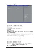
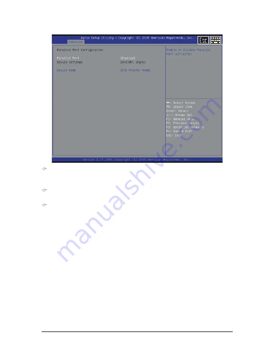
2-2-1-2 Parallel Port Configuration

  Parallel Port  


When enabled allows you to configure the parallel settings. 


Options available: Enabled/Disabled. Default setting is 

Enabled

.

  Device Settings 


Display the specified Parallel port base I/O addressand IRQ.

  Device Mode  


Configure parallel port mode.


STD Printer Mode: Similar to Standard Parallet Port mode, but  STD Printer Mode only provides one 

direction data flow communication.  


Standard Parallet Port mode (SPP): SPP stands for Standard Parallet Port. Differ from Standard (STD) 
Printer Mode is this mode provides bi-direction data flow communication. Set this item to SPP Mode, 

system will transfer protocol for the parallel port. It works all parallel devices.


EPP Mode: Enhanced Parallel Port using existing parallel port signals to provide a asymmetric bidirec-
tional communication. It's offering transfer rates of up tp 2MB/s. 


ECP Mode: The Extended Capabilities Port transfer mode uses DMA protocol to achieve data transfer 
rates of up tp 2MB/s and provides symmetric bidirectional communication. 


EPP -1.9 and SPP Mode: Enable EPP 1.9 and SPP Mode.


EPP -1.7 and SPP Mode: Enable EPP 1.7 and SPP Mode.


ECP and EPP 1.9 Mode: Enable ECP and EPP 1.9 Mode.


ECP and EPP 1.7 Mode: Enable ECP and ECP 1.7 Mode.


Options available: STD Printer Mode/SPP Mode/EPP 1.9 and SPP Mode/EPP 1.7 and SPP Mode/


ECP Mode/ECP and EPP 1.9 Mode/ECP and EPP 1.7 Mode. 


Default setting is 

STD Printer Mode

.

Summary of Contents for MZBSWAI

Page 1: ...MZBSWAI Intel Celeron Processor N3150 User s Manual Rev 1001 ...

Page 2: ...d features in this manual may be made by GIGABYTE without prior notice No part of this manual may be reproduced copied translated transmitted or published in any form or by any means without GIGABYTE s prior written permission Documentation Classifications Inordertoassistintheuseofthisproduct GIGABYTEprovidesthefollowingtypesofdocumentations For detailed product information carefully read the User...

Page 3: ...onnectors 13 Chapter 2 BIOS Setup 24 2 1 The Main Menu 26 2 2 Advanced Menu 28 2 2 1 Super IO Configuration 29 2 2 1 1 Serial Port Configuration 30 2 2 1 2 Parallel Port Configuration 31 2 2 2 Hardware Monitor 32 2 2 3 S5 RTC Wake Settings 33 2 2 4 CPU Configuration 34 2 2 4 1 CPU Information 35 2 2 5 SATA Configuration 36 2 2 6 OS Selection 37 2 3 Chipset Menu 38 2 4 Security Menu 40 2 4 1 Secure...

Page 4: ...eld Standard 44 45mm Low Profile 25 54mm One Screw The box contents above are for reference only and the actual items shall depend on the product package you obtain The box contents are subject to change without notice The motherboard image is for reference only ...

Page 5: ... 5 MZBSWAI Motherboard Layout 1 2 3 4 5 6 7 8 9 10 12 13 14 15 16 17 18 19 20 21 22 23 24 25 26 27 28 29 30 31 32 33 11 ...

Page 6: ... 15 LCD_VCC LVDS Drive voltage jumper 16 FPD_PWR LVDS power select jumper 12V 19V 17 SYS_FAN System fan connector 18 SYS_PANEL Front panel header 19 MS_SW Monitor power switch header 20 LVDS LVDS connector 21 FPD Flat Panel Display connector 22 BL_SW Back light brightness switch 23 FUSB2_1 USB 2 0 header 24 SO_DIMM DDR3 SO DIMM slot 25 FUSB2_2 USB 2 0 header 26 COM1 Serial port cable connector 27 ...

Page 7: ... 7 Block Diagram ...

Page 8: ...y and first touch a metal object to eliminate static electricity Prior to installing the motherboard please have it on top of an antistatic pad or within an electrostatic shielding container Before unplugging the power supply cable from the motherboard make sure the power supply has been turned off Before turning on the power make sure the power supply voltage has been set according to the local v...

Page 9: ...e Interface 2 x SATA 6Gb s connector USB 4 x USB 3 0 port back panel 3 x USB 2 0 headers 3 additional ports via the USB brackets connected to the internal USB headers Internal Connectors 1 x 2 pin power connector 2 x SATA 6Gb s connector 1 x SATA HDD power connector 1 x CPU fan header 1 x System fan header 1 x System panel header 1 x Back Light Brightness header 1 x Audio header 3 x USB 2 0 header...

Page 10: ...er the CPU system fan speed control function is supported will depend on the CPU system cooler you install BIOS AMI BIOS Form Factor Thin Mini ITX Form Factor 170CM x 170CM GIGABYTE reserves the right to make any changes to the product specifications and product related information without prior notice ...

Page 11: ...nt hardware damage Memory modules have a foolproof design A memory module can be installed in only one direction If you are unable to insert the memory switch the direction 1 3 1 Installing a Memory Installation Step Step 1 Align the memory with the SO DIMM module and insert the SO DIMM memory module into the SO DIMM slot Please note that memory module has a foolproof insertion design A memory mod...

Page 12: ...phone or front surroundspeakers can be connected to Line Out Front Speaker Out jack MIC In Pink The default MIC In jack Microphone cab be connected to MIC In jack When After installing the HDMI device make sure the default device for sound playback is the HDMI device The item name may differ by operating system Refer the figures below for details and enter BIOS Setup then set Onboard VGA output co...

Page 13: ...ines before connecting external devices First make sure your devices are compliant with the connectors you wish to connect Before installing the devices be sure to turn off the devices and your computer Unplug the power cord from the power outlet to prevent damage to the devices After installing the device and before turning on the computer make sure the device cable has been securely attached to ...

Page 14: ...panel module mainly consists of power switch reset switch power LED hard drive activity LED and etc When connecting your chassis front panel module to this header make sure the wire assignments and the pin assignments are matched correctly Pin No Signal Name Definition 1 HD Hard Disk LED Signal anode 2 MPD Power LED Signal anode 3 HD Hard Disk LED Signal cathode 4 MPD Power LED Signal cathode 5 GN...

Page 15: ...ion 1 GND 2 TXP 3 TXN 4 GND 5 RXN 6 RXP 7 GND 3 4 FUSB2_1 FUSB2_2 USB 2 0 Headers The headers conform to USB 2 0 1 1 specification Each USB header can provide two USB ports via an optional USB bracket For purchasing the optional USB bracket please contact the local dealer Pin No Definition 1 VCC 2 USB 3 USB 4 GND 5 No Pin 1 1 9 2 10 5 FUSB2_2 FUSB2_1 FUSB2_1 FUSB2_2 Pin No Definition 1 Power 5V 2 ...

Page 16: ...io HD and AC 97 audio You may connect your chassis front panel audio module to this header Make sure the wire assignments of the module connector match the pin assignments of the motherboard header Incorrect connection between the module connector and the motherboard header will make the device unable to work or even damage it Pin No Definition 1 MIC_L 2 GND 3 MIC_R 4 ACZ_DET 5 HPOUT_R 6 F_MIC_JD ...

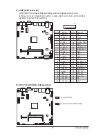
Page 17: ...cting the output of a video controller in a laptop computer computer monitor or LCD television set to the display panel Most laptops LCD computer monitors and LCD TVs use this interface internally The headers conform to FPD specification 1 8 Pin No Definition 1 BKLT_EN 2 BKLT_PWM 3 BKLT_PWR 4 BKLT_PWR 5 BKLT_GND Brightness_GND 6 BKLT_GND Brightness_GND 7 Brightness_Up 8 Brightness_Down ...

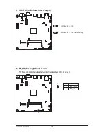
Page 18: ...LVDS Power Select Jumper 1 2 Close Set to 12V 2 3 Close Set to 19V Default setting 1 1 10 BL_SW Back Light Switch Header The Back Light switch provides the function for screen back light adjustment 1 2 Pin No Definition 1 BL_DOWN 2 BL_UP ...

Page 19: ...O3_C 2 RXO3_C 3 RXO2_C 4 RXO2_C 5 RXO1_C 6 RXO1_C 7 RXO0_C 8 RXO0_C 9 RXE3_C 10 RXE3_C 11 RXE2_C 12 RXE2_C 13 RXE1_C 14 RXE1_C 15 RXE0_C 16 RXE0_C 17 GND 18 LCD_VCC 19 LCD_VCC 20 LCD_VCC Pin No Definition 21 NC 22 VCC3 23 GND 24 LVDS_SENSE 25 GND 26 RXECLKO_C 27 RXECLKO_C 28 GND 29 GND 30 GND 31 SCL1 32 SC_BKLT_EN 33 SC_BKLTCTL 34 RXECLKE_C 35 RXECLKE_C 36 FPD_19V 37 FPD_19V 38 FPD_19V 39 NC 40 SD...

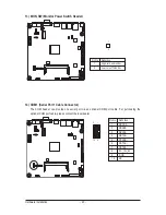
Page 20: ...w turn off monitor 14 COM1 Serial Port 1 Cable Connector The COM header can provide one serial port via an optional COM port cable For purchasing the optional COM port cable please contact the local dealer Pin No Definition 1 NDCDA 2 NDSRA 3 NRXDA 4 NRTSA 5 NTXDA 6 NCTSA 7 NDTRA 8 RI _12V_5V 9 GND 10 NC 1 9 2 10 ...

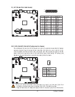
Page 21: ...g a fan cable be sure to connect it in the correct orientation the black connector wire is the ground wire The motherboard supports CPU fan speed control which requires the use of a CPU fan with fan speed control design For optimum heat dissipation it is recommended that a system fan be installed inside the chassis Pin No Definition 1 GND 2 12V 3 Sense 4 Speed Control 1 Be sure to connect fan cabl...

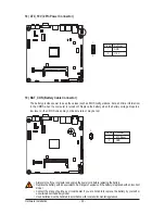
Page 22: ...s to a low level or the CMOS values may not be accurate or may be lost Always turn off your computer and unplug the power cord before replacing the battery Replace the battery with an equivalent one Danger of explosion if the battery is replaced with an incorrect model Contact the place of purchase or local dealer if you are not able to replace the battery by yourself or uncertain about the batter...

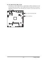
Page 23: ...ormation and BIOS configurations and reset the CMOS values to factory defaults To clear the CMOS values place a jumper cap on the two pins to temporarily short the two pins or use a metal object like a screwdriver to touch the two pins for a few seconds Open Normal operation Default setting Close Clear CMOS data ...

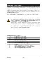
Page 24: ... with caution Inadequate BIOS flashing may result in system malfunction It is recommended that you not alter the default settings unless you need to to prevent system instability or other unexpected results Inadequately altering the settings may result in system s failure to boot If this occurs try to clear the CMOS values and reset the board to default values Refer to the Restore Defaults section...

Page 25: ...ation of boot sequence Security Change set or disable supervisor and user password Configuration supervisor password allows you to restrict access to the system and BIOS Setup A supervisor password allows you to make changes in BIOS Setup A user password only allows you to view the BIOS settings but not to make changes Save Exit Save all the changes made in the BIOS Setup program to the CMOS and e...

Page 26: ... displayed on the bottom line of the Main Menu Submenu Help While in a submenu press F1 to display a help screen General Help of function keys available for the menu Press Esc to exit the help screen Help for each item is in the Item Help block on the right side of the submenu When the system is not stable as usual select the Restore Defaults item to set your system to its defaults The BIOS Setup ...

Page 27: ...e when the BIOS setup utility was created LAN MAC Address Displays the LAN MAC address information Memory Information Total Memory Display the total memory size of the installed memory TXE FW Version Display the TXE firmware version System Date Set the date following the weekday month day year format System Time Set the system time following the hour minute second format ...

Page 28: ... Setup 28 2 2 Advanced Menu The Advanced menu display submenu options for configuring the function of various hardware components Select a submenu item then press Enter to access the related submenu screen ...

Page 29: ...S Setup 2 2 1 Super IO Configuration Super IO Configuration Serial Port Configuration Press Enter for configuration of advanced items Parallel Port Configuration Press Enter for configuration of advanced items ...

Page 30: ...Serial Port When enabled allows you to configure the serial port settings When set to Disabled displays no configuration for the serial port Options available Enabled Disabled Default setting is Enabled Device Settings Display the specified Serial Port base I O addressand IRQ ...

Page 31: ...his item to SPP Mode system will transfer protocol for the parallel port It works all parallel devices EPP Mode Enhanced Parallel Port using existing parallel port signals to provide a asymmetric bidirec tional communication It s offering transfer rates of up tp 2MB s ECP Mode The Extended Capabilities Port transfer mode uses DMA protocol to achieve data transfer rates of up tp 2MB s and provides ...

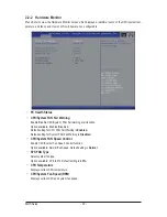
Page 32: ...lert funciton Option available Enabled Disabled Default setting for CPU FAN Fail Warning is Enabled Default setting for System FAN Fail Warning is Disabled CPU System FAN Speed Control Enable CPU System Fan Speed Control function Option available Normal Full Speed Default setting is Normal SYS FAN Type Select system fan type Option available 3 Pin 4 Pin Default setting is 4 Pin CPU Temperature Dis...

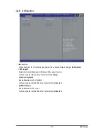
Page 33: ...led System will wake on the hr min sec specified Default setting is Disabled Wake up hour Note Press and to define the wake up hour Wake up minute Note Press and to define the wake up minute Wake up second Note Press and to define the wake up second Note This item appears when Wake system from S5 is set to Fixed time ...

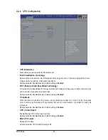
Page 34: ...th voltage and frequency in tandem between high and low levels in response to processor load Options available Enabled Disabled Default setting is Enabled Turbo Mode When this feature is enabled the processor can dynamically overclock one or two of its four processing cores to improve performance with applications that are not multi threaded or optimized for quad core processors Options available ...

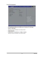
Page 35: ...ocode Path Processor Cores Intel HT Technology Intel VT x Technology Displays the technical specifications for the installed processor Cache Information L1 Data Cache L1 Code Cache L2 Cache L3 Cache Displays the technical specifications for the installed processor ...

Page 36: ... detect HDD type Hot Plug for Serial SATA Port 0 1 2 3 4 5 Enable Disable Hot Plug support for Serial ATA Port 0 1 Options available Enabled Disabled Default setting is Disabled External SATA Chip The category identifies Serial ATA and mSATA types of hard disk that are installed in the computer System will automatically detect HDD type Note that the specifications of your drive must match with the...

Page 37: ... Support Determine Compatibility Support Module CSM support function Options available Never Always Default setting is Always LAN PXE OpROM Enable Disable LAN PXE OpROM Options available Enabled DIsabled Default setting is Disabled LAN EFI driver Enable Disable LAN EFI driver Options available Enabled DIsabled Default setting is Disabled ...

Page 38: ...raphics Memory size used by the Internal Graphics Device Options available 64M 128M 192M 256M 320M 384M 512M Default setting is 64M ERP Lowest Power State Mode Enable Disable ERP Lowest Power State Mode Options available Enabled Disabled Default setting is Disabled Restore AC Power Loss This option provides user to set the mode of operation if an AC power loss occurs Power On System power state wh...

Page 39: ...800 x 600 18 bit Single channel 1024 x 600 18 bit Single channel 1024 x 768 18 bit Single channel 1024 x 768 24 bit Single channel 1280 x 800 24 bit Single channel 1280 x 1024 18 bit Dual channel 1280 x 1024 24 bit Dual channel 1366 x 768 18 bit Single channel 1366 x 768 24 bit Single channel 1600 x 900 18 bit Dual channel 1600 x 900 24 bit Dual channel 1920 x 1800 18 bit Dual channel 1920 x 1800 ...

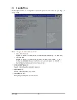
Page 40: ...disable this field a Administrator Password must first be set A user can only access and modify the System Time System Date and Set User Password fields AdministratorPassword Press Enter to configure the Administrator password User Password Press Enter to configure the user password Secure Boot menu Press Enter for configuration of advanced items 2 4 Security Menu The Security menu allows you to s...

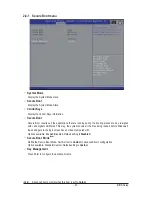
Page 41: ...is way the system knows all the files being loaded before Windows 8 loads and gets to the login screen have not been tampered with Options available Enabled Disabled Default setting is Disabled Secure Boot Mode Note Define the Secure Boot Mode Set this item to Custom to advanced items configuration Option available Standard Custom Default setting is Custom Key Management Press Enter to configure t...

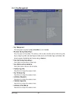
Page 42: ...x Options available Enabled Disabled Default setting is Disabled Enroll All Factory Default Keys Press Enter to install all factory default keys Save All Secure Boot Variables Press Enter to save all Secure Boot Variables Platform Key PK Press Enter to configure the advanced items Key Exchange Key Press Enter to configure the advanced items Authorized Signature Press Enter to configure the advance...

Page 43: ...essage if the drive s specified is not bootable Boot Configuration Boot Option Priorities Boot Option 1 2 3 Press Enter to configure the boot priority By default the server searches for boot devices in the following secquence 1 UEFI device 2 Hard drive 3 Network device Hard Drive BBS Priorities Press Enter to configure the boot priority ...

Page 44: ... Options available Yes No Restore Defaults Loads the default settings for all BIOS setup parameters Setup Defaults are quite demanding in terms of resources consumption If you are using low speed memory chips or other kinds of low performance components and you choose to load these settings the system might not function properly Options available Yes No Boot Override Press Enter to configure the d...

Reviews: