background image

8

E

P

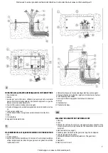
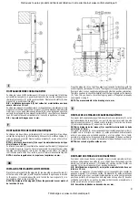
MAMPOSTERÍA DE LA PLACA DE ANCLAJE DEL MORORREDUCTOR

  1

  2

  3

  4

  5

  6

  7

  8

  9

10

Pavimentación.

Piés.

Vainas para cables ø 25 mínimo. Para la protección de los cables

uitlizar vainas de dimensiones adecuadas de tipo pesado

aprobado; las vainas deben estar recubiertas de cemento.

Cables eléctricos (ver predisposiciones en pág. 5).

Placa de anclaje para la regulación de la altura del motorreductor.

Tubo para pasar los cables.

Abrazaderas para la regulación horizontal del motorreductor.

Tuercas.

Motorreductor.

Equipo electrónico.

ALVENARIA DA PLACA DE FIXAÇÃO DO MOTORREDUTOR

  1

  2

  3

  4

  5

  6

  7

  8

  9

10

Piso.

Peças de fixação.

Tubos para cabos Ø 25 mín. Para a protecção dos cabos usar

tubos de dimensões adequadas, de tipo pesado aprovado. Os

tubos devem ser cobertos de cimento.

Cabos eléctricos (v. predisposição na pág. 5)

Chapa de fixação para a regulação da altura do motorredutor.

Tubo para passagem dos cabos.

Abraçadeiras para a regulação horizontal do motorredutor.

Porcas

Motorredutor

Cartão para a ligação do motor e dos fins-de-curso magnéticos.

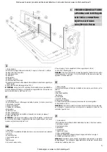
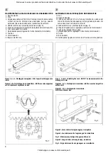
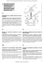
Figure 1,  2  e 4 - Montaggio cremagliera - N.B.: le quote sul disegno sono

in mm

Figures 1, 2 et 4 - Montage de la crémaillière - NOTA: Les cotes rappelées

sur le croquis sont exprimées en mm.

Figs. 1, 2 and 4 - Installing the rack - NOTE: The measurements in the

drawing are in mm

Figuras 1, 2 y 4 - Montaje de la cremallera - NOTA: Las cotas del gráfico

están en mm

Figuras 1, 2 e 4 - Montagem da cremalheira.

N.B. Dimensões em mm.

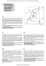
Figura 3 - Gioco minimo tra ingranaggio e cremagliera

Figure 3 - Jeu minimum entre l’engrenage et la crémaillere

Fig. 3 - Minimum play between the gear and the rack

Figura 3 - Jeugo mínimo entre engranaje y cremallera

Fig. 3 - Folga mínima entre a engrenagem e a cremalheira.

Fig. 4

Retrouvez tous les produits du fabricant Gibidi sur notre site internet www.confort-electrique.fr

Téléchargé sur www.confort-electrique.fr

Summary of Contents for Pass 12 Plus

Page 1: ...O ISO 9002 Cert n 0079 MOTORIDUTTORE PASS 4 6 12 18 PLUS CON APPARECCHIATURA ELETTRONICA PLUS 1 INCORPORATA MOTOREDUCTEUR PASS 4 6 12 18 PLUS AVEC PLATINE ELECTRONIQUE PLUS 1 INCORPOREE MOD PASS 4 6...

Page 2: ...one external 3 Antenna 4 Pneumatic strip 5 Push button panel 6 Rack 7 Key selector 8 Screened coaxial cable 9 Power supply line to equipment follow regulations in force 10 220 230 V flashing light WAR...

Page 3: ...EDUCTOR MONTAGEM DO MOTORREDUTOR PASS 4 6 PASS 12 18 Dimensioni di ingombro in mm Dimensions en mm Overall dimensions are in mm Dimensiones m ximas en mm Dimens es em mm Retrouvez tous les produits du...

Page 4: ...aines appropri es du type approuv Les gaines doivent tre rev tues de ciment C bles lectriques voir les appareillages lectriques la page 5 Plaque de fixation permettant de r gler le motor ducteur en ha...

Page 5: ...a regula o da altura do motorredutor Tubo para passagem dos cabos Abra adeiras para a regula o horizontal do motorredutor Porcas Motorredutor Cart o para a liga o do motor e dos fins de curso magn ti...

Page 6: ...orrespond horizontally with the small magnet 1 installed on the card The magnets 2 are polarized differently from each other one has negative polarization and other has positive polarization Therefore...

Page 7: ...tement and connection The safety device with inductive sensor 1 allows electronic control of the mechanical and electronic PASS 4 torque limiter If the gate intercepts an obstacle in the closing and o...

Page 8: ...r the PASS 12 18 gearmotors into the socket 2 Remember that turning the wrench clockwise increases the thrust and turning it counterclockwise decreases the thrust If the shaft also rotates when you tu...

Page 9: ...The key 3 will be pushed out a few millimeters by a spring Then completely turn the handle 1 180 towards the left You can now manually open and close the gate To automatically reset it turn the handle...

Page 10: ...14 e 13 Cavo coassiale dell antenna del radioricevitore Collegare la calza o schermatura al morsetto 18 ed il filo centrale al morsetto 17 Programmazione Programmatore montato sul radioricevitore a sc...

Page 11: ...menta zione generata all interno della scheda ed disposta in modo da garantire il rispetto dell isolamento doppio o rinforzato rispetto alle parti in tensione Tutti gli ingressi vengono gestiti dall a...

Page 12: ...nal earth wire N C contact of the stop button Connect to terminals 11 13 N O contact terminals 10 and 13 of the button for the sequential open stop close command or vice versa or opening only when swi...

Page 13: ...istrateur Delegu Tiziano Toselli CE DECLARATION OF CONFORMITY FOR MACHINES Directive 89 392 EEC Attachment II part B PROHIBITION OF OPERATION The manufacturer Gi Bi Di Continental Srl Via Abetone Bren...

Reviews: