DSC100
11
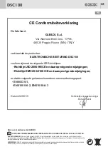
CE Declaration of conformity
The manufacturer:
GI.BI.DI. S.r.l.
Via Abetone Brennero, 177/B,
46025 Poggio Rusco (MN) ITALY
declares that the products:
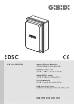
ELECTRONIC CONTROL UNIT DSC100
are in conformity with the following CEE Directives:
•
• EMC Directive 2004/108/CE and subsequent amendments;
and that the following harmonised standards have been applied:
• EN60335-1,
• EN61000-6-2, EN61000-6-3
Date 24/09/2018
LVD Directive 2006/95/CE and subsequent amendments;
The legal Representative
Michele Prandi
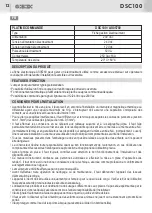
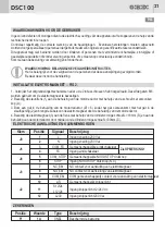
SETTINGS - JUMPER SW1
DEFAULT SETTINGS
Jumper
SW1
Position
ON
State
Function
Description
SW1
ON
OFF
IRREVERSIBLE
SYSTEM
REVERSIBLE
SYSTEM
See proper section
See proper section
FUNCTIONING
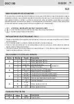
Connect the electromagnet between terminals 8 and 9. In the absence of power supply 230 Vac the gate is free to
move. When the control unit AS05780 is powered you have the following options.
IRREVERSIBLE SYSTEM (SW1 = ON)
Powering the control unit AS05780 the electromagnet activates blocking the gearmotor and therefore making the
system irreversible. The electromagnet will remain active until the power supply of the control unit will be present.
You can connect to the STOP input a push button with reset. By pushing the STOP button you will turn off
the electromagnet making the system reversible. To reactivate the electromagnet will be necessary to reset the
STOP button.
In this mode the FC input is not active
REVERSIBLE SYSTEM (SW1 = OFF)
It is necessary to enable the PRE-FLASHING function on the control board of the gearmotor.
Powering the control unit AS05780 the electromagnet remains not active leaving the system reversible .
The electromagnet activation, with locking of the gearmotor and irreversible system, will happen only by a
consequence of the presence of the flashing light signal of the gearmotor control unit.
The electromagnet will remain active until the flashing light signal will be present and it will turn off 1 s after the
disappearance of the signal.
In this way the electromagnet is deactivated both when the gate is in pause (opening phase completed) and the gate
is in sleep (closing phase completed)
You can always keep the gate blocked in open and/or closed position by using a limt switch wired to the FC input.
Be careful that the limit switch must active before the end of the gate movement.
NOTE 1:
The limit switch wired to the input 3 and 4 is NOT the limit switch for stopping the motor. It's simply an
auxiliary device which must be activated before the activation of the limit switch which cause the gate movement to
stop.
DSC100
10
UK
UK
WARNINGS:
This product has been tested in GI.BI.DI. verifying the perfect correspondence of the characteristics to the current directive.
GI.BI.DI. S.r.l. declares
that the products to which this handbook refers comply with the essential requirements of the following DIRECTIVES
EMC 2004/108/CE - LVD 2006/95/CE. The entire declaration is available at www.gibidi.com.
DISPOSAL:
GI.BI.DI. advises recycling the plastic components and to dispose of them at special authorised centres for electronic
components thus protecting the environment from polluting substances.
PLEASE READ CAREFULLY THIS MANUAL BEFORE PROCEEDING WITH THE INSTALLATION.
Thank you for choosing GI.BI.DI.

