background image

Pressure in the discharge line and pump must 

be at zero before any maintenance to the pump 

takes place.  Shut off suction line.  Disconnect 

fuses to ensure that the driving motor does not 

get switched on accidentally.  Make sure that all 

parts on the pressure side of the unit are vented 

before starting the pump.  In order to prevent air, 

or an air-water mixture being absorbed and to 

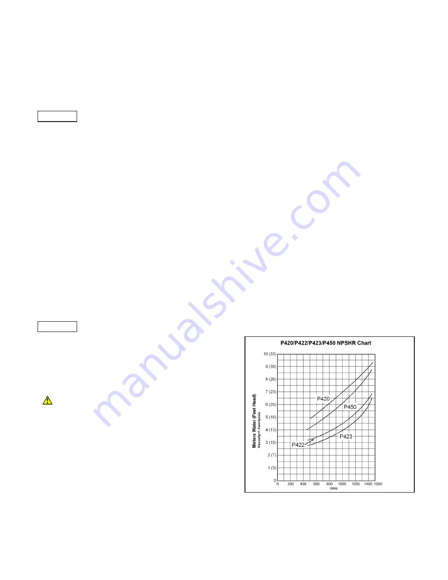
prevent cavitation occurring, the pump NPSHR 

(=suction head) and water temperature must be 

respected.

Cavitation and/or compression of gases lead 

to uncontrollable pressure kicks which can 

ruin pump and unit parts and also be dan-

gerous to the operator or anyone standing 

nearby. 


Giant Plunger Pumps are suitable for pumping 

clean water and other non-agressive or non-

abrasive media with a specific weight similar to 

water.

Before pumping other liquids - especially 

inflammable, explosive and toxic media - the 

pump manufacturer must be consulted with 

regard to the resistance of the pump mate-

rial.  It is the responsibility of the equipment 

manufacturer and/or operator to ensure that 

all pertinent safety regulations are ahered to.

2

INSTALLATION INSTRUCTIONS

Required NPSH refers to water (specific weight 1kg/

dm

3

) at maximum permissible pump revolutions.

Operation and Maintenance

Check oil level prior to starting to ensure trouble-free 

water supply.

Important!

  If there is a 

danger of frost

, the water 

in the pump and in the pump fittings (particularly the 

unloader valve) must be emptied.  The second dis-

charge port cal also be used and the pump run “dry” 

for 1-2 minutes for this purpose.

Oil amount: 30.4 ounces (0.9 liters).  Only use 

ISO 

VG 220 industrial gear oil

 (e.g. Aral Degol BG220) 

or 

automobile gear oil SAE 90 GL4 

(Giant p/n 

01154).

Initial oil change after 50 operating hours and then 

every 500 hours, after 1 year if used less.  Caution 

when operating in damp places or with high temper-

ature fluctuations.  Oil must be changed immediately 

should condensate (frothy oil) occur in the gear box.

NPSH values must be observed.

Maximum input pressure 145 PSI (10 bar), maxi-

mum suction head -4.35 PSI (-0.3 bar).  Make sure 

that suction pulsation is sufficiently dampened - wa-

ter column resonance must be avoided.

Important! 

 If the pump is not used for a long period 

of time, it is possible the seals (23/23B) could be-

come hard or brittle thus causing the pump to leak 

when put into operation.

If this is the case, we recommend these seals be 

replaced every 4 years.

Safety Rules

A safety valve is to be installed in accordance with 

the guidelines for liquid spraying units so that the 

admissible operating pressure cannot be exceeded 

by more than 10%.  Pump operation without a safety 

vlave as well as any excess in temperature or speed 

limits automatically voids the warranty.

When the pump is in operation, the drive shaft end 

and the coupling must be enclosed by a protective 

cover or a coupling bell.

Summary of Contents for P400 Series

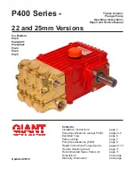
Page 1: ...Kits page 7 Pump Specifications P425 page 8 Repair Instructions Torque Specs pages 9 10 Trouble Shooting Chart page 11 Recommended Spare Parts List page 11 Dimensions back page Warranty Information back page Updated 06 18 Triplex Ceramic Plunger Pump Operating Instructions Repair and Service Manual For Models P420 P420 0011 P420 0021 P422 P423 P425 ...

Page 2: ...Important If there is a danger of frost the water in the pump and in the pump fittings particularly the unloader valve must be emptied The second dis charge port cal also be used and the pump run dry for 1 2 minutes for this purpose Oil amount 30 4 ounces 0 9 liters Only use ISO VG 220 industrial gear oil e g Aral Degol BG220 or automobile gear oil SAE 90 GL4 Giant p n 01154 Initial oil change aft...

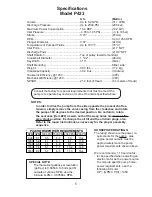
Page 3: ...e or more of the limits specified above SPECIAL NOTE The theoretical gallons per revolution gal rev is 0 00883 To find specific outputs at various RPM use the formula GPM 0 00883 x RPM U S Metric Volume Up to 12 8 GPM 48 4 L min Discharge Pressure Up to 2175 PSI 150 bar Maximum Power Consumption 19 2 BHP 14 3 kW Inlet Pressure 4 35 to 145 PSI 3 to 10 bar Stroke 0 945 24mm RPM Up to 1450 RPM Plunge...

Page 4: ...formula HP GPM X PSI 1450 SPECIAL NOTE The theoretical gallons per revolution gal rev is 0 00683 To find specific outputs at various RPM use the formula GPM 0 00683 x RPM Specifications Model P422 U S Metric Volume Up to 9 9 GPM 37 3 LPM Discharge Pressure Continuous Up to 2610 PSI 180 bar Discharge Pressure Intermittent Up to 3000 PSI 200 bar Maximum Power Consumption 17 7 BHP 13 2 kW Inlet Press...

Page 5: ...mp horse power requirements use the following formula HP GPM X PSI 1450 SPECIAL NOTE The theoretical gallons per revolution gal rev is 0 00566 To find specific outputs at various RPM use the formula GPM 0 00566 x RPM Specifications Model P423 U S Metric Volume Up to 8 2 GPM 31 1 LPM Discharge Pressure Up to 2900 PSI 200 bar Maximum Power Consumption 16 4 BHP 12 2 kW Inlet Pressure 4 35 to 145 PSI ...

Page 6: ...6 EXPLODED VIEW P420 P420 0011 P420 0021 P422 P423 AND P425 PUMPS ...

Page 7: ...23B 12255 0010 Weep Seal Viton J 3 23B 12255 0020 Weep Seal Teflon K 3 23B 13390 Weep Seal B G 3 24 08376 Pressure Ring A H J K 6 24 06252 Pressure Ring B G 3 25 08394 Weep Return Ring A H J K 3 25 06254 Weep Return Ring B G 3 26 08395 Manifold 1 27A 08408 Valve Assembly A B G H 6 27A 08408 0001 Valve Assembly J K 6 27 08370 Valve Seat 6 28 06791 0100 Valve Plate 6 29 06377 0100 Valve Spring 6 30 ...

Page 8: ...equirements use the following formula HP GPM X PSI 1450 SPECIAL NOTE The theoretical gallons per revolution gal rev is 0 00738 To find specific outputs at various RPM use the formula GPM 0 00738 x RPM Specifications Model P425 U S Metric Volume Up to 10 7 GPM 40 4 LPM Discharge Pressure Up to 2465 PSI 170 bar Maximum Power Consumption 18 1 BHP 13 5 kW Inlet Pressure 4 35 to 145 PSI 3 to 10 bar Str...

Page 9: ...27 and the valve spring retainer 30 the valve assembly can be separated 4 Remove the o ring 31 Inspect all parts for wear and replace as necessary Apply one drop of loctite 243 to the valve plugs 32 and tighten to 107 ft lbs 145 NM 5 Use a 8mm allen wrench to remove the 8 socket head cap screws 34 Carefully slide the valve casing 26 out over the plungers 6 Remove seal case 20 and weep return rings...

Page 10: ...08092 Plug with Gasket 59 ft lbs 80 Nm 6 01010 Screw 111 in lbs 12 5 Nm 10 07114 Screw with Washer 133 in lbs 15 Nm 15B 05349 Connecting Rod Screw 97 in lbs 11 Nm 16D 08399 Tensioning Screw Loctite 243 20 7 ft lbs 28 Nm 32 08373 Plug Loctite 243 107 ft lbs 145 Nm 34 08396 Cap Screw Lightly Oil 30 ft lbs 40 Nm Repair Instructions P420 P420 0011 P420 0021 P422 P423 and P425 11 If oil leaks under und...

Page 11: ...sure Drop leaks correctly sized inlet plumbing to pump Accumulator pressure Recharge Replace accumulator Unloader Check for proper operation Cavitation Check inlet lines for restrictions and or proper size Pressure Drop at Gun Restricted discharge plumbing Re size discharge plumbing to flow rate of pump Excessive Worn plungers Replace plungers Leakage Worn packing seals Adjust or Replace packing s...

Page 12: ...tions made by the customer or third party 6 The operation of pumps and or accessories exceeding the specifications set forth in the Opera tions Manuals provided by Giant Industries Inc Liability under this warranty is on all non wear parts and limited to the replacement or repair of those products returned freight prepaid to Giant Industries which are deemed to be defective due to workmanship or f...

Reviews: