3
7. Maintenance and Servicing
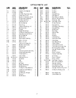
For the type of thread lock used and the required
tightening torques, observe the table in the exploded
view.
7.1 Special tools required
The following special tools are required for
assembly:
- Pull-out tool ø24 mm
- Seal extractor tool ø22.4 mm
7.2 Suction and Discharge Valves
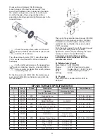
Remove hexagon screw (58) and remove valve
casing (54). Pull seal case (38) out of valve casing
(54). Pull valve body (52) and seal case (38) apart.
Using pliers, pull spring guide (55) out of the
valve casing. Remove discharge valve plate (57)
together with spring (56) from spring guide (55).
Check sealing surfaces of the valve body (52) and
discharge valve plate (57). Check discharge valve
spring (56) and border seal ring (53) and replace
where necessary.
A damaged border seal ring (53) must be
replaced before reassembling.
Suction Valves
Remove suction valve spring (50) with valve plate
(51) from seal case (38). Check sealing surfaces
of the valve plate (51) and valve body (52).
Check O-rings (38/A/B/C) and support ring
(38D) before reassembling. Worn parts must be
replaced
.
To Check Seals and Plungers
Unscrew hexagon screws (58), and take off valve
casing (54). Remove the screw-in joints (70) and
take off the elbow pipes (72). Pull seal sleeve
(39/39A) out of the crankcase.
Take the seal tension spring (40) out of seal
sleeve (39/39A).
Using a pliers, remove the clip ring (48) situated
on the other side of the sleeve; then take out
support ring (47) and grooved ring (46) using an
extractor tool (ø24).
Using a seal extractor tool (ø22.4), carefully press
the seal unit comprising guide ring (44), spiral
ring (42) and support ring (41/43) out of the seal
sleeve (39/39A) from the side (39/39A) closest to
the drive.
Check spiral ring (42),Support ring (43), guide
ring (44) and grooved ring (46) and replace where
necessary.


