2
Safety Rules
Pump operation without safety valve as well
as any excess in temperature or speed limits
automatically voids the warranty. The safety
valve must be regulated in accordance with
the guidelines for liquid spraying units so that
the admissible operating pressure can not be
exceeded by more than 10%.
When the pump is in operation, the open shaft
end must be covered up by shaft protector (21)
and the driven shaft side and coupling by a bell
housing; the plunger room should have a cover
(30).
Before any maintenance to the pump takes
place, the pressure in discharge line and in
pump must be at zero. Close up suction line.
Disconnect fuses to ensure that the driving
motor does not get switched on accidently.
Make sure that all parts on the pressure side of
the unit are vented and refilled, with pressure at
zero, before starting the pump.
In order to prevent air or an air/water-mixture
being absorbed and to prevent cavitation
occurring, the pump-npshr (positive suction head
and water temperature) must be kept under
control.
Cavitation and/or compression of gases
lead to uncontrollable pressure-kicks which
can ruin pump and unit parts and also
be dangerous to the operator or anyone
standing nearby.
Giant plunger pumps are suitable for pumping
clean water and other non-aggressive or
abrasive media with a specific weight similar to
water.
Before pumping other liquids - especially
inflammable, explosive and toxic media
- the pump manufacturer must, under all
circumstances, be consulted with regard to
the resistance of the pump material. It is the
responsibility of the equipment manufacture
and/or operator to ensure that all pertinent
safety regulations are adhered to.
Standard pump with valve casing of seawater-
resistant-bronze.
Figures given for maximum pressure and maximum
speed (rpm) apply to interval operation. When the
pump is used in continual operation and/or with
water warmer than 104°F (40°C), these values must
be reduced by 10%.
Required NPSH refers to water: Specific weight
1kg/dm3, viscosity 1
o
E at maximum permissible
revolutions, using both suction connections.
IMPORTANT!
Use of both suction connections
is imperative in order to ensure cavitation-free
operation and optimal suction conditions. If only one
connection is used, a safety margin of one meter
has to be added to the required NPSH.
Operation and Maintenance
Check oil level prior to starting and ensure trouble-
free water supply.
IMPORTANT!
If there is a
danger of frost
,
the water in the pump and in the pump fittings
(particularly the unloader valve) must be emptied.
The second discharge port can also be used and the
pump run “dry” for 1-2 minutes for this purpose.
Oil amount:
1.6 gallons (6.0 litres). Only use
Giant’s p/n 01154 or
ISO VG 220 industrial gear
oil
(e.g. Aral Degol BG220) or
automobile gear oil
SAE 90 GL4.
We recommend ISO VG 68 (SAE80) gear oil for low
ambient temperatures (+41°F/5°C and less).
Initial change after 50 operating hours and then
every 1000 operating hours, or after 1 year if used
less.
IMPORTANT!
When operating in damp places
or with high temperature fluctuations, oil must be
changed immediately, should condensate (frothy oil)
occur in the gear box.
IMPORTANT!
If the pump is mounted on a vehicle
(possibility of unlevelness) and/or if the pump speed
is between 300 rpm and 500 rpm, the oil quantity is
1.8 gallons (7.0 liters). To check, put the oil dipstick
in the bore situated beside the eye bolt.
Keep NPSH under control.
Maximum input pressure 145 PSI (10 bar),
maximum suction head -4.35 PSI (-0.3 bar). Make
sure that suction pulsation is sufficiently dampened –
water column resonance must be avoided.
INSTALLATION INSTRUCTIONS
Summary of Contents for GP7142
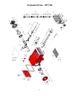
Page 4: ...4 Exploded View GP7142...

