background image

9

 7)  

 Be careful not to damage the seal 

sleeve (39) and pressure ring (41).  Check the inner  

diameter of the pressure ring for wear and if neces-

sary replace together with seals (40) and (42). Clean 

all parts. New parts should be lightly coated with 

silicon grease before installation. Insert the seal unit 

(40, 41, 42 43) into the sleeve. Push the ceramic 

plunger carefully through the seals from the crank-

case side. If necessary, the seals can be held tightly 

using a suitable pipe support held on the other side 

of the seal sleeve.

8)  Take out the seal case (38) from the valve 

casing (50) and check o-rings (38A) (if necessary 

secure two screwdrivers in the front o-ring groove 

to extract seal casing  from valve casing). Coat 

seals with silicon grease before installing.

 Mounting surfaces of the crankcase 

and the valve casing must be clean and free of 

damage. The components must lie exactly and 

evenly on one another. The same exactness ap

-

plies for all centering positions in the crankcase, 

pressure and valve casing.

9)  Coat the seal sleeve(39) lightly with anti-corrosive 

grease (e.g. molycote no.Cu-7439) in its fitted area 

towards the crankcase. Insert the seal sleeves in to 

their crankcase fittings. Coat the threads of the ten

-

sion screw (36C)  lightly with thread glue and insert 

it together with a new copper ring (36D) through 

the ceramic pipe. Turn the pump by hand until the 

plunger (25) rests against the plunger pipe.  Tighten 

the tension screw at 30 Ft-lbs. (40 NM)

 Thread glue must never come between 

the plunger pipe (36B) and centering sleeve (36E). 

Overtensioning of the plunger pipe by excessive 

tightening of the tension screw and/or dirt or damage 

on the mounting surfaces can lead to plunger pipe 

breakage. Insert the seal tension spring (45) and o-

ring (39A) in to the seal sleeve (39).  

Replacing Valve Casing:

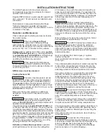
10) Put seal cases (38) in the centering holes of the 

valve casing, then push valve casing carefully on to 

centering studs (50A). Tighten hexagon screws (49A) 

evenly and crosswise at 265 Ft.-lbs. (360 NM).  Follow 

pattern below.


  The torque tension on the screws (49A) 

must be checked after 8-10 operating hours; the pump 

must be at zero pressure.  Thereafter, the tension is to 

be checked every 200 operating hours.

Pump Repair Instructions - GP8155/GP8160/GP8165  

Summary of Contents for GEARBOX Series

Page 1: ...7 Repair Instructions pages 8 10 Troubleshooting Chart page 11 Torque Specifications page 11 Dimensions back page Warranty Information back page Triplex Ceramic Plunger Pump Operating Instructions Repair and Service Manual Series GP8155 1000 GP8160 1000 GP8165 1000 GEARBOX SERIES GP8100 Spheroidal Nickel Plated Cast Iron Manifold GP8100 1000 Bronze Manifold Updated 03 22 ...

Page 2: ...MPORTANT The service life of the seals is maximized if a minimal amount of leckage is present A few drops of water can drip from each plunger every minute Leakage has to be examined every day the plunger seals must be changed should leckage become excessive constant dripping INSTALLATION INSTRUCTIONS The stated figures are for maximum pressure and maximum speed rpm and apply for interval operation...

Page 3: ...y maintenance work to the pump or unit Close off suction line Disconnect fuses to ensure that the driving motor cannot get switched on accidently Make sure that the pump the cooling system and all parts on the pressure side of the unit are vented and refilled with pressure at zero before starting the pump In order to prevent air or an air water mixture being absorbed and cavi tation occurring the ...

Page 4: ...t of head GP8155 75 5 3000 580 145 2 17 23 GP8160 90 2500 580 147 2 36 23 6 GP8165 105 6 120 2000 580 658 142 166 2 55 26 2 Max Flow Maximum Pressure Maximum Speed Power Required Plunger Diameter NPSHR Model L min Bar RPM kW mm mWs GP8155 285 200 580 108 55 7 0 GP8160 337 170 580 110 60 7 2 GP8165 400 455 140 580 658 106 123 65 8 0 U S Measurements Metric Measurements U S Metric Maxiumum Inlet Pre...

Page 5: ...65 09586 Item Part Description Qty 38A 06667 O Ring 6 39A 05066 O Ring 3 40 06996 Seal Ring 3 42 06997 V Sleeve 9 Inlet Valve Kit 09587 Item Part Description Qty 51B 05078 Inlet Valve Seat 1 51C 05079 Valve Plate 1 51D 07658 O Ring 1 51E 05080 Valve Spring 1 56A 06258 O Ring 1 Discharge Valve Kit 09588 Item Part Description Qty 52B 05084 Discharge Valve Seat 1 52C 05079 Valve Plate 1 52D 06258 O R...

Page 6: ...6 Exploded View GP8155 GP8160 GP8165 ...

Page 7: ...leeve Support Ring GP8155 3 43 05070 Sleeve Support Ring GP8160 3 43 05118 Sleeve Support Ring GP8165 3 Item Part Description Qty 45 05279 Seal Tension Spring GP8155 3 45 05071 Seal Tension Spring GP8160 3 45 05119 Seal Tension Spring GP8165 3 49 05072 Stud Bolt 8 49A 05073 Hexagon Nut 8 50 05074 Valve Casing GP8155 GP8160 GP8165 1 50 05074 3000 Valve Casing 1000 Versions 1 50A 13162 Centering Stu...

Page 8: ... for any damage Coat o rings 51D 52D 56A with silicone grease to help with re assembly Replace valve assembly 51 and pressure spring 57 Assemble valve assembly 52 to discharge valve adapter 56 by tapping together lightly with rubber mallet While replacing the valve assemblies use a rubber mallet to tap the top of the valve puller lightly This insures proper seat ing Replace pressure spring 57A and...

Page 9: ...sleeve 39 lightly with anti corrosive grease e g molycote no Cu 7439 in its fitted area towards the crankcase Insert the seal sleeves in to their crankcase fittings Coat the threads of the ten sion screw 36C lightly with thread glue and insert it together with a new copper ring 36D through the ceramic pipe Turn the pump by hand until the plunger 25 rests against the plunger pipe Tighten the tensio...

Page 10: ...onger be turned by hand Then remove a shim and establish whether the crankshaft can now be turned A crankshaft that can be too easily turned may cause damage to the bearings 20 21 and connecting rods 24 due to the wobble movements in the conical bearing shells If bearings 20 21 have been replaced the flange 19 must be taken off and a new bearing outer ring pressed in until the surfaces are even Th...

Page 11: ... Shaft seal ring leaks Check seal and shaft Noise increases without the loss Worn bearing Dismantle gear examine all parts replace worn parts check oil level If service life was too short check for excess strain or whether lubrication intervals were too long Only specified lubricants are to be used Troubleshooting GP8155 GP8355 GP8160 GP8360 GP8165 GP8365 TOOL LIST AND TORQUE SPECIFICATIONS Item P...

Page 12: ... or modifications made by the customer or third party 6 Theoperationofpumpsandoraccessoriesexceedingthespecificationssetforth in the Operations Manuals provided by Giant Industries Inc Liability under this warranty is on all non wear parts and limited to the replacement or repair of those products returned freight prepaid to Giant Industries which are deemed to be defective due to workmanship or f...

Reviews: