background image


Fig 2 

 
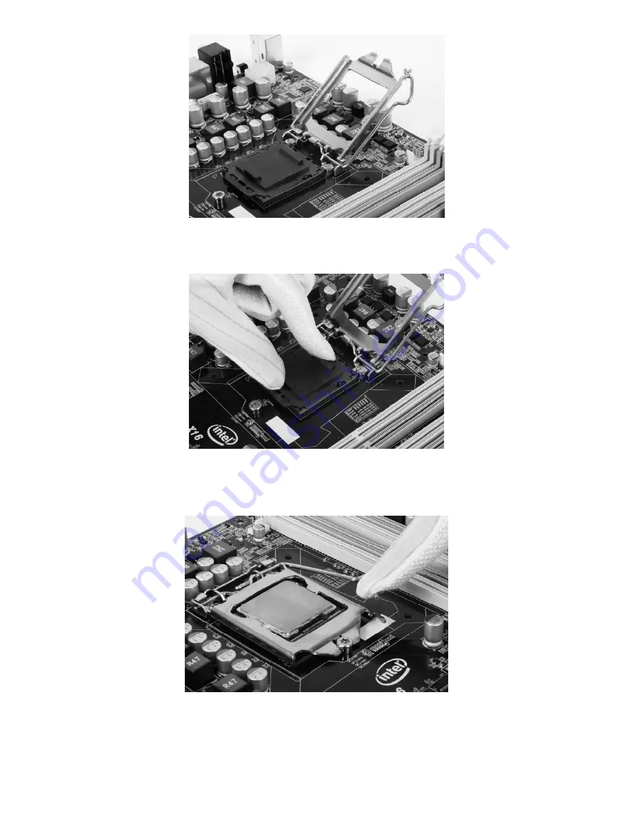
1.3 Uncover the contact pin protect cover, as shown in Fig.3 


Fig 3 

 
1.4 Input the CPU carefully; make sure the contact pins in socket and contact lands on CPU are matched. Close 
the cover, as shown in Fig 4   


Fig 4 


1.5 Then you need to lock down the socket lever while gently press the metal shell with your fingers. When 
lock process has been complete, you will hear a crisp sound.


Summary of Contents for Mini-ITX

Page 1: ...Giada Mini ITX Motherboard User s Manual Version 001 All rights reserved...

Page 2: ...Standard BIOS Setup 3 Advanced Advance BIOS Setup 3 1 CPU configuration 3 2 IDE configuration 3 3 IO Chipset configuration 3 4 PC Health configuration 4 Power 5 Booting 6 Security setup 7 Setup for c...

Page 3: ...ncluding mini PC tablet PC motherboard and graphics card etc GIADA combines the idea of fashion to its products and wishes people can enjoy the style of fashion and art while using the products under...

Page 4: ...TX power supply of the motherboard make sure the switch of the power supply is in OFF state Installing the motherboard onto the computer case For most of the computer cases the multiple fixing holes l...

Page 5: ...carefully make sure the contact pins in socket and contact lands on CPU are matched Close the cover as shown in Fig 4 Fig 4 1 5 Then you need to lock down the socket lever while gently press the meta...

Page 6: ...o lock down the socket lever while gently press the metal shell with your fingers When lock process has been complete you will hear a crisp sound Fig 6 1 7 Installing CPU FAN Only with the desired coo...

Page 7: ...power cable into the socket on the motherboard 2 Installing Memory Please install the memory in accordance with the following procedures 2 1 Remove the white buckle at the two ends of the interface s...

Page 8: ...ce in that process 3 Install expansion slot card 3 1 Install graphic card This motherboard provides one interface slot for PCIE 16x AGP When you install the PCIE graphic card you should note that groo...

Page 9: ...E slot may locate in not same place and support different type device please reference in quick installation guide or ask your distributor 4 Layout of motherboard Please reference in quick installatio...

Page 10: ...t the parameters in BIOS Therefore the correct setup of BIOS plays a key role in stably running the system and optimizing its performance The CMOS Setup will save the set parameters in the built in CM...

Page 11: ...e main interface of Setup the major selected contents will be displayed at the lower part of the interface with the change of the options Set interface When you set the value for each column you can v...

Page 12: ...facilities CPU HDD etc 3 Power power management This item is used for setting ACPI advanced configuration and power management such as sleep mode S1 S3 wake up method By USB PS 2 4 Chipset setting th...

Page 13: ...s item to set the time for the computer with the format as hour minute second 3 System date mm dd yy Use this item to set the date for the computer with the format as week month day year 3 Advanced Ad...

Page 14: ...3 Adjacent Cache Line Prefech High speed adjacent cache prefetch function Disabled Enabled 4 Intel Virtualization Technology 5 CPU C3 Report 6 CPU C6 Report 7 Package C State Limit Energy conservatio...

Page 15: ...does not support AHCI mode AHCI mode could only be use in built in operating system like Windows Vista or Windows 7 3 Aggressive Link Power Management Options Disabled Enabled You could do further SAT...

Page 16: ...item you can view the state of the system hardware You can view the speed of the CPU fan temperature of CPU and other values 2 CPU Fan Speed Control To set the CPU fan s mode Options Auto Full On Mode...

Page 17: ...and methods 4 Restore AC power loss This item is used for setting what state the system should be in when the AC power is restored after power interruption The options and their definitions are as fol...

Page 18: ...Fig 4 10 This item includes North bridge and South bridge configuration 5 1 North Bridge configuration Fig 4 11 1 Total Memory This item is use to set memory frequency...

Page 19: ...aphic Adapter This item is use to set display controller Default PEG IGD 5 2 South Bridge configuration Fig 4 12 1 Azalia HD Audio 2 Azalia Internal HDMI codec Do enable this item when HDMI output is...

Page 20: ...Fig 4 13 1 CPU Tuning 2 Memory Tuning 3 ICC OverClocking This is an over clocking item use to set CPU clock speed 7 Boot...

Page 21: ...re OFF and ON In other words this item can be used for setting the state of Num Lock for the time the system has been started It can be set on the basis of the needs of the user and doesn t affect the...

Page 22: ...set program of BIOS If set as Setup the password will be required to be entered only before the system goes to the set program of BIOS To delete the password press Enter in the popped up window that r...

Page 23: ...Save changes and exit Discard changes and reset 2 Restore defaults Save as user defaults Restore as user defaults...

Page 24: ...r you complete the installation of the operating system you should then install the driver for the motherboard To this end put the disk into the CD ROM The interface as shown in Fig 1 will appear Fig...

Page 25: ...shown in Fig 3 will pop up Then you can click Next and wait till the driver is installed completely Fig 3 4 2 Install Sound card driver After you click Install behind the Realtek HD audio driver in t...

Page 26: ...in Fig 5 will pop up Then you can click Next and wait till the driver is installed completely Fig 5 4 4 Installing driver for graphic card To install the driver for graphic card you can click Install...

Page 27: ...or Windows XP SP3 1 The control panel of the audio adapter will appear after the driver is installed as shown in Fig 7 Fig 7 2 After the initial installation of the driver the default state of microph...

Page 28: ...manually as shown in Fig 8 and 9 Fig 8...

Page 29: ...Fig 9 For Windows Vista 1 After the driver for the audio adapter is stalled you can click the Audio Manager at the lower right corner The initial interface will pop up as shown in Fig 10 and 11 Fig 10...

Page 30: ...t of the control interface Advanced Setup for Device the interface shown in Fig 12 will pop up Then select separate all input jacks as independent input devices 3 Click OK and the controlling interfac...

Page 31: ...the device as default In the above interface you can adjust the volume for recording and the playing volume for the MIC 5 If you need to set the output of multi channel you should right click the mou...

Page 32: ...Fig 14 6 Select Redistribution of Connectors Then an interface will pop up as shown in Fig 15 After that set the corresponding output Fig 15...

Page 33: ...elevision reception which can be determined by turning the equipment off and on the user is encouraged to try to correct the interference by one or more of the following measures Reorient or relocate...

Reviews: