background image

18

17

Key

↑ (Up key)

↓ (Down key)

← (Left key)

→ (Right key)

ESC 

Page Up

Page Down

F1

F7

F8

F9

F10

Function

Move to the previous item

Move to the next item

Move to the left item

Move to the right item

Exit the current interface

Change the setup state, or add the values

Change the setup state, or deduct the values

Display the information of the current setup

Load the set values of previous time

Load the safest values

Load the optimized values

Save the settings and exit the CMOS SETUP 

C.Auxiliary information
Main interface
When the system enters the main interface of Setup, the major selected contents 
will be displayed at the lower part of the interface with the change of the options.
Set interface
When you set the value for each column, you can view the preset value of the 
column and the values that can be set if you press F1, for example, the BIOS 
default values or CMOS Setup values. To exit the interface for auxiliary information, 
press [ESC].

To enter BIOS, you can press F1; to load the default values and enter the system, 

you can press F2. After the self-detection process is completed, you can press 

DEL to enter the BIOS interface if no error is found. If the indicative information 

disappears before you can act, you can shut off the computer and turn on it 

again, or you can press the key RESET on the machine case. To restart your 

computer, you can also simultaneously press <Ctrl>+<Alt>+<Delete>.

B. Function Keys definitions
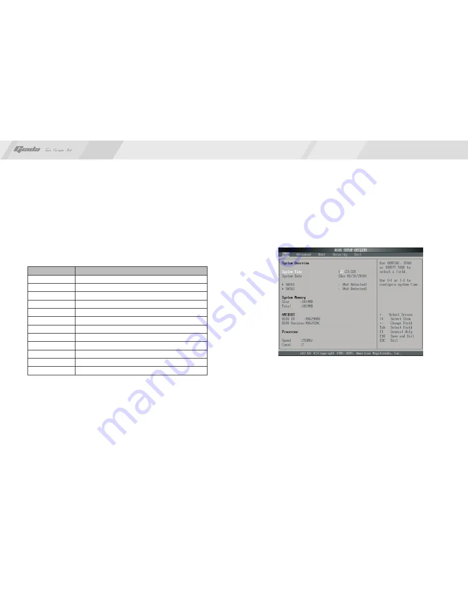
1. Main menu

When the system enters the CMOS Setup menu, you can see the main menu on 

the upper part of the screen, as shown in Figure 3.1. In this main menu, you can 

use the left and right direction keys to select the setup items. Once the item is 

selected, the lower part of the computer screen will show the details of setting.

(The options above and their contents may be different from your actual options, 

so they are used for reference only).

· 

Main (standard CMOS setup)

This item is used for setting the date, time, specifications of hard disk and floppy 

disk and type of monitor.

· 


Advanced (advanced BIOS setup)

This item is used for setting the advanced functions provided by BIOS, such as 

the virus alarm and priority order of disks for startup process.

Fig 3.1

www.giadatech.com

Summary of Contents for MI-D525

Page 1: ...www giadatech com User s Manual MI D525 All right reserved Version 001 Motherboard...

Page 2: ...Pins for front end audio adapter 3 6 ATX 12V 12V Power receptacle 3 7 F_ PANEL Front end control panel 4 Rear panel interface Contents III BIOS setting 1 Main menu 2 Main standard CMOS setup 3 Advance...

Page 3: ...5 It supports DDR3 800 Dual channel memory on board HD AUDIO sound card Support USB2 0 Any question about the product please send e mail to our support center Headquarter Sales giadatech com support g...

Page 4: ...components These ICs might be damaged by the static charge Therefore the user must make the following preparations before installation Turn off the power of the computer It is preferable the power co...

Page 5: ...omputer is turned off before the memory or other component is installed or removed As the groove is set at the golden finger of the DDR DIMM the memory can only be inserted into the slot with one dire...

Page 6: ...3 CLR_CMOS CMOS pin The correct time system hardware and other information are saved in the CMOS memory of the motherboard The interruption the computer s power won t cause the loss of this informatio...

Page 7: ...st Note Don t connect the wire to Pin 4 The definitions of the ports are described below Definition GND 5V NULL PIN 2 4 6 8 10 Definition MIC MIC BIAS OUT R GND OUT L PIN 1 3 5 7 9 2 10 1 9 www giadat...

Page 8: ...anel Definition PLED PW_LED PWRBTN GND PLED PIN 2 4 6 8 10 Definition HDLED HDLED RST RST RST PIN 1 3 5 7 9 www giadatech com Definition 3 3V 12V GND PS ON GND GND GND 5V 5V 5V PIN 11 12 13 14 15 16 1...

Page 9: ...erves as the only channel that connects the hardware and software whether your computer can run stably and work in optimized state will hinge on how to properly set the parameters in BIOS Therefore th...

Page 10: ...es and enter the system you can press F2 After the self detection process is completed you can press DEL to enter the BIOS interface if no error is found If the indicative information disappears befor...

Page 11: ...value discard changes discard changes and exit 2 Main standard CMOS setup System time hh mm ss Use this item to set the time for the computer with the format as hour minute second System date mm dd y...

Page 12: ...for setup If it is set as Disable that line of English words won t appear However if the words wait appear during the start up process and you press Del the system can also enter CMOS for setup Hit De...

Page 13: ...p program directly when the system is restarted Boot Sector Virus Protection This item is used for setting the alarm function in the case of virus attack in IDE disk sector If this item is set as Enab...

Page 14: ...motherboard After you complete the installation of the operating system you should then install the driver for the motherboard To this end put the disk into the CD ROM The interface as shown in Fig 4...

Page 15: ...Install Sound card driver After you click Install behind the Realtek HD audio driver in the interface 1 1 Installing driver for Chipset After you click Install behind the Intel Chipset driver in the i...

Page 16: ...in the Fig 4 5 Driver in the interface of Fig 4 2 complete the installation by following the indications in the popped up dialog boxes and then restart the computer 1 4 Installing driver for graphic...

Page 17: ...fault state of microphone is mute You need to turn it on manually as shown in Fig 4 7 and 4 8 After the driver for the audio adapter is stalled you can click the Audio Manager at the lower right corne...

Page 18: ...nput jacks as independent input devices Fig 4 10 Fig 4 11 www giadatech com Click OK and the controlling interface will turn to one shown in Fig 4 12 If a MIC is used please select the corresponding f...

Page 19: ...ght click the mouse at the corresponding output interface A dialog box will pop up as shown in Fig 4 13 Fig 4 13 www giadatech com Select Redistribution of Connectors Then an interface will pop up as...

Page 20: ...radio or television reception which can be determined by turning the equipment off and on the user is encouraged to try to correct the interference by one or more of the following measures Reorient o...

Reviews: