


LPPYRA13
- 13 -
V2.3
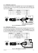
4.2
LPPYRA13AC
CONNECTIONS
The pyranometer LPPYRA13AC has 4…20 mA output and requires 10…30 Vdc exter-
nal power supply. It is to be connected to a power supply and an instrument with
4…20 mA input as shown in fig. 4.2. The load resistance of the instrument reading the
signal must be
≤
500
Ω
.
Connector
Function
Color
1
Positive (Iin)
Red
2
Negative (Iout)
Blue
3
Housing
White
4
Cable shield
Black
Fig. 4.2: LPPYRA13AC connections
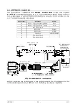
4.3
LPPYRA13AV
CONNECTIONS
The pyranometer LPPYRA13AV has 0…1 V, 0…5 V or 0…10 V output (depending on
the ordered output) and requires external power supply: 10…30 Vdc for 0…1 V and
0…5 V outputs, 15…30 Vdc for 0…10 V output. It is to be connected to a power sup-
ply and an instrument with voltage input as shown in fig. 4.3. The load resistance of
the instrument reading the signal must be
≥
100 k
Ω
.
Connector
Function
Color
1
Output positive (+Vout)
Red
2
Output negative (-Vout)
Power supply negative (GND)
Blue
3
Power supply positive (+Vdc)
White
4
Cable shield
Black
Fig. 4.3: LPPYRA13AV connections
CPM12AA4… cable
Sensor M12
male connector
Power supply
10…30 Vdc
Red [1]
Blue [2]
Black [4]
White [3]
Connect to ground only if it is not possible to
ground locally the case of the pyranometer
Instrument with
4…20 mA input
CPM12AA4… cable
Sensor M12
male connector
Power supply
Red [1]
Blue [2]
Black [4]
White [3]
Instrument
with
voltage input
15…30 Vdc for 0…10V output
10…30 Vdc for 0…1/5V output
Summary of Contents for Delta OHM LPPYRA13
Page 32: ...LPPYRA13 32 V2 3 NOTES...
Page 33: ...LPPYRA13 33 V2 3 NOTES...
Page 34: ...LPPYRA13 34 V2 3 NOTES...
Page 35: ......


