


LPPYRA13
- 14 -
V2.3
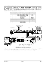
4.4
LPPYRA13S
CONNECTIONS
The pyranometer LPPYRA13S has RS485 Modbus-RTU output and requires
5…30 Vdc external power supply. It is to be connected to a power supply and to a
PLC, a data logger or a RS485/USB or RS485/RS232 converter for PC as shown in fig.
4.4. The RS485 output is not isolated.
Connector
Function
Color
1
Power supply negative (GND)
Blue
2
Power supply positive (+Vdc)
Red
3
Not connected
4
RS485 A/-
Brown
5
RS485 B/+
White
6
Housing
Shield (Black)
7
Not connected
8
Not connected
Fig. 4.4: LPPYRA13S connections
Before connecting the pyranometer to the RS485 network, set the address and the
communication parameters, if different from the factory preset (see chapter 6).
Pyranometer
Surge
Protector
Housing
RS485
output
Power supply
Power supply
5…30 Vdc
Red
Blue
Brown
White
CPM12-8D… cable
Pyranometer M12
male connector
PLC, data logger or
RS485/USB or
RS485/RS232
converter for PC
Other sensors with
RS485 output
Termination
Termination
Shield
Connect to ground only if it is not possible
to ground locally the case of the pyranometer
Summary of Contents for Delta OHM LPPYRA13
Page 32: ...LPPYRA13 32 V2 3 NOTES...
Page 33: ...LPPYRA13 33 V2 3 NOTES...
Page 34: ...LPPYRA13 34 V2 3 NOTES...
Page 35: ......


