background image

Summary of Contents for Speedy Spread

Page 1: ...ALL HYDRAULIC TRUCK SPEADER OPERATORS MANUAL 1 800 277 4337 WWW GFESPEEDYSPREAD COM REVISED 2009 ...

Page 2: ...6 299 4711 FAX NUMBER 336 854 5796 SHIPPING ADDRESS GFE 429 EDWARDIA DR GREENSBORO NC 27409 BILLING ADDRESS GFE PO BOX 19409 GREENSBORO NC 27419 PLEASE NOTE PARTS ORDERS PLACED BY 2 PM WILL BE SHIPPED SAME DAY AS ITEMS ARE AVAILABLE VISIT US ON THE WEB AT WWW SPEEDYSPREAD COM ...

Page 3: ...ute when spreading fertilizer This insert is stored on the passenger side of the spreader body near the rear Another important item is spinner speed Generally spinner speed should not exceed 800 RPM Ideal spinner speed is 750 RPM The spinner speed is checked by using a hand held tachometer The Mid Tech 6100 series is equipped with a fan RPM sensor that allows the speed to be monitored on the contr...

Page 4: ...he spread width in inches Information should only be entered in BOOM 1 Mid Tech 6000 and 6100 Distance Calibration Quick Guide Mark off 400 feet in a straight line Put mode selector switch on Operate Turn the selector to Distance Use the DEC switch to zero out the total distance Position truck at the first marker of the 400 foot path Put mode selector on Operate Leave the selector to Distance Driv...

Page 5: ...2 location on the console Raven Distance Calibration Quick Guide Mark off 400 feet in a straight line Position truck at the first marker of the 400 foot path Press the Distance key Enter 0 for the distance Drive the 400 foot path at a constant speed Stop at the end of the 400 foot path The console will show you a number that is close to 400 feet it may be over or under To get the new calibration n...

Page 6: ...ess YES to exit the program then press EXIT TO MENU then select VIPER PRO 9 Repeat step 2 You will not lose any product information 10 To start a job Press MENU START JOB NEW JOB or FROM FILE if it is a new job the job will be auto named with today s date if you wish to change the name press and input your new job name Then press NEXT 11 Product Selection Screen Press NEXT 12 Product 1 Setup Scree...

Page 7: ...TO SET THE RATE AND PRODUCT NAME SELECT RATE CONTROL 6 PRESS TO SELECT THE PRODUCT YOU WILL BE USING THEN PRESS TO ACCEPT AND RETURN TO THE PREVIOUS PAGE 7 PRESS TO SET THE APPLICATION RATE USE THE ON SCREEN KEY PAD AND THEN PRESS TO ACCEPT THE RATE 8 PRESS THE TO ACCEPT THE PRODUCT SETUP NOTE IF YOU ARE USING A VARIABLE RATE PRESCRIPTION MAP YOU WILL NEED TO PRESS TO ACCESS A LIST OF MAPS SELECT ...

Page 8: ...ADER CONSTANT GATE CALIBRATION PRESS TO RETURN TO THE CALIBRATION SCREEN 15 PRESS TO ACCEPT CHANGES 16 PRESS TWO MORE TIMES TO GET BACK TO THE APPLICATION SCREEN USE THE CHAIN MASTER SWITCH TO TURN THE BED CHAIN ON AND OFF CLOSING THE JOB AND POWERING OFF THE ENVIZIO 1 PRESS THEN TO EXIT THE JOB 2 PRESS TO CLOSE THE JOB 3 PRESS TO CONFIRM CLOSING THE JOB 4 TO START A NEW JOB GO TO STEP 1 5 TO POWE...

Page 9: ...ou must not move the truck as this will kick you out of self test With the PTO engaged rev the truck to operating RPMs and turn on the Master Switch The chain will be moving at this point Keep the truck at operating RPMs until the spreader is almost empty Turn off the Master Switch to stop the chain Weigh the truck again and subtract your original weight to find out how much material has actually ...

Page 10: ...here system switches between using Valve Response 1 and Valve Response 2 increase to slow response time default 15 Allowable Error error allowed before making rate control adjustments Shaft Speed Calibration pulses revolution of metering shaft Max Speed maximum allowable RPM of product conveyor Servo Valve There is a tab for every channel of control with Control Valve Configurations and related se...

Page 11: ...er will not stop rotating default 30 Automatic Control select to control the spinner speed Spinner Tab PWM Frequency frequency valve is pulsed at settings come from manufacturer typical range 100 125 Hz PWM Gain decrease to slow response time Zero Flow Offset duty cycle used to start moving conveyor if setting is too high conveyor will not turn off default 30 Allowable Error error allowed before m...

Page 12: ...here the Rate Control Settings screen is explained Product Control Toolbox Target Rate 1 2 preset application rates that allow a quick change between rates Manual Valve Control allows operator manual control of valve Prescription allows rates to be determined by a loaded prescription Up and Down Arrows allow rates to be adjusted manually Settings button opens Rate Control Settings screen explained...

Page 13: ... and down arrows in the Product Control Toolbox Prescription press to load a map based prescription file Bin Full press to fill container Bin Partially Filled press to specify container amount Bin Empty press to empty container Tank Alarm Setting can set remaining or amount remaining for low container alarm To access the Rate Control Settings window ...

Page 14: ... circuit while machine is stationary In Field Calibration performs automated routine to adjust the calibration number for the selected metering circuit if there is a difference between the amount of product logged compared to what was actually applied Product Density value lb ft3 is stored for each product Use the numeric keypad to edit value Feed Gate Opening measure depth of product on conveyor ...

Page 15: ...on Number For 360 Rear Shaft Rate Sensor Gate Setting Cal Gate Setting Cal 1 do not use 5 5 516 5 2 do not use 6 473 4 2 5 1136 4 6 5 437 0 3 946 9 7 405 8 3 5 811 5 7 5 378 7 4 710 2 8 355 0 4 5 631 2 8 5 334 3 5 568 1 9 315 5 Gate Calibration Number For 180 Raven Rear Shaft Rate Sensor Gate Setting Cal Gate Setting Cal 1 do not use 5 5 NA 2 710 6 237 2 5 NA 6 5 NA 3 473 7 203 3 5 NA 7 5 NA 4 355...

Page 16: ...ou must not move the truck as this will kick you out of self test With the PTO engaged rev the truck to operating RPMs and turn on the Master Switch The chain will be moving at this point Keep the truck at operating RPMs until the spreader is almost empty Turn off the Master Switch to stop the chain Weigh the truck again and subtract your original weight to find out how much material has actually ...

Page 17: ...d hose 1 Drivers Side Front Corner and Front Pipe Hydraulics Ref Part Description Qty Ref Part Description Qty 1 S 6 54 x 45 male adapter 1 1 S 6 61 x 45 female adapter 1 2 S 6 39 x 15 hyd hose 1 2 S 6 39 x 15 hyd hose 1 3 S 6 49 female adapter 2 3 S 22 14 6x6x4 pvc box 1 4 S 6 16 service tee 1 5 S 6 26 x 36 hyd hose 1 6 S 6 130 x 23 hyd hose 1 7 S 6 29 x 84 hyd hose 1 7 S 6 60 X 96 hyd hose 1 7 S...

Page 18: ...0 st elbow 1 ns S 6 62K valve repair kit 1 Ref Part Description Qty 1 S 6 6 relief valve 1 2 S 6 27 x 26 hyd hose 1 3 S 6 54 x 45 male adapter 2 4 S 6 39 x 15 hyd hose 1 5 S 6 49 female adapter 1 6 S 6 39 x 15 hyd hose 1 Ref Part Description Qty 1 S 22 21 EXRII hyd valve 1 1a S 22 21C EXRII manifold only 1 2 S 22 22 EXRII bracket 1 3 S 6 181 str x bushing 1 4 S 6 54 x 45 male adapter 1 5 S 6 183 s...

Page 19: ... 6 142 hyd oil filter assembly 1 6 S 6 135 oil level sight plug 1 7 S 6 53 x 90 female adapter 1 8 S 6 4 hyd oil tank 1 Ref Part Description Qty 1 S 6 168 2 x 1 suction strainer 1 2 GI 781 1 x 3 nipple 1 3 S 6 33 1 gate valve 1 4 GI 613 1 x close nipple 1 5 GI 701 1 elbow 1 6 F 100 1 hose barb 1 7 F 118 1 hose clamp 1 8 S 6 63 1 suction hose per ft ...

Page 20: ...rawson gearbox 1 2 S 22 20 gearbox sensor 1 3 S 22 19 sensor ext cable 1 4 S 6 121 x 18 hyd hose 2 5 S 7 17I allen head socket cap screw 2 6 S 7 15A gasket 3 7 S 7 15 spacer 1 8 S 6 183 str x x 90 male adapter 1 9 S 6 181 str x bushing 1 10 S 6 54 x 45 male adapter 1 11 S 7 16 char lynn motor 1 12 S 6 182 7 16 str x bushing 1 13 S 6 128 x 90 male adapter 1 14 S 6 210 x 17 hyd hose 1 ns S 7 17C rep...

Page 21: ... for shaft adapter 1 Spinner Plate Assembly Ref Part Description Qty 1 S 4 29S right plate ss 1 S 4 29 right plate steel 1 S 4 30S left plate ss 1 S 4 30 left plate steel 2 S 4 26 right blade 3 2 S 4 27 left blade 3 2 S 4 80 right hard blade 3 2 S 4 81 left hard blade 3 3 S 4 68 blade bolt kit 1 ns S 4 83 plate bolt kit 1 ...

Page 22: ... 11 spinner hub 2 7 S 5 6 key 2 8 S 5 5 seal 2 Note Please specify if your spinner housing has a Fan RPM Sensor mount Spinner Motor Assembly Ref Part Description Qty 1 S 6 212 spinner motor 2 2 S 6 54 x 45 male adapter 2 3 S 6 39P x 15 high pressure hyd hose 1 4 S 6 129 x 31 hyd hose 1 5 S 6 92 x 30 hyd hose 1 6 S 6 35 tee 1 7 S 6 97 nipple 1 8 S 6 118 x busing 1 9 S 6 128 x 90 male adapter 2 10 S...

Page 23: ...y 1 1a S 29 8 fast valve complete 1 2 S 6 39 18 x hyd hose 1 3 S 6 18 21 x hyd hose 2 4 S 6 47 male adapter 1 5 S 6 54 x 45 male adapter 1 6 S 6 50 x 90 male adapter 1 Ref Part Description Qty 1 063 0171 071 rate sensor 1 Ref Part Description Qty 1 117 0159 575 fan RPM sensor 1 ...

Page 24: ...onveyor chain 11 body 1 10b S 2 27 conveyor chain 13 body 1 11 S 1 143 wipe out brush 1 12 S 4 33 side shield 2 13 N 26 0075 3 8 x ss bolt 4 14 N 26 0003 3 8 ss flat washer 4 ns N 26 0002 3 8 ss lock washer 4 ns N 26 0001 3 8 ss nut 4 Ref Part Description Qty 1 S 2 21 idler sprocket w shaft 1 2 S 6 140 90 x zerk fitting 2 3 S 2 10 1 take up bearing 2 4 S 2 19 1 ss flat washer 2 5 S 2 17 take up ro...

Page 25: ...S 4 32 ss flat washer 2 6 S 4 53 bearing 1 7 S 4 55 handle w hardware 1 ns S 4 66 pointer 1 ns N 26 0125 3 8 x 1 ss bolt 2 ns N 26 0001 3 8 ss nut 2 ns N 26 0002 3 8 ss lock washer 2 ns N 26 0003 3 8 ss flat washer 2 ns N 24 0075 x ss bolt 4 ns N 24 0002 ss lock washer 4 Ref Part Description Qty 1 S 4 42 insert 1 2 S 12 4 s hook 2 3 S 12 7 rubber strap 1 ...

Page 26: ...t Description Qty 1 S 1 33 gate rod 1 2 S 1 38 gate 1 3 N 26 0001 3 8 ss nut 10 4 S 1 35 gate nut holder 1 5 S 1 98R right gate track 1 6 N 24 0075 x ss bolt 6 7 S 1 35A ss cotter pin 1 8 S 1 23 gate shear strip 1 9 N 26 0150 3 8 x 1 ss bolt 6 10 S 1 5A ss screw 2 11 S 1 5 gate scale 1 12 S 1 99L left gate track 1 13 N 26 0002 3 8 ss lock washer 10 14 S 1 34 gate rod nut 1 15 N 26 0003 3 8 flat wa...

Page 27: ...s 2 6 SY 1 87 narrow pin stripe per foot 7 S 1 16 GFE decal 2 8 S 1 48 danger decal 1 9 SY 1 84 wide pin stripe per foot 10 S 14 3 3 light bar 1 Ref Part Description Qty 1 S 14 1 amber corner light 2 2 S 14 5 amber round reflector 2 3 S 1 48 oil tank decal 1 4 GP 731 oil tank cap 1 5 S 6 98 oil tank breather cap 1 6 S 1 22 plexiglas window 1 7 S 1 20 speedy spread decal 1 ...

Page 28: ...ble 1 Radar Ref Part Description Qty 1 S 22 15 radar shield 1 2 S 22 4 radar 1 3 S 22 17 radar cable 1 Mid Tech Console Ref Part Description Qty 1 S 25 1 6100 console 1 2 S 22 1A console bracket 1 3 S 22 12 status switch box 1 4 S 17 16 console stand 1 ________________________________________________ Spinner RPM Sensor Ref Part Description Qty 1 S 23 3 spinner RPM sensor 1 2 S 23 6 RPM sensor moun...

Page 29: ...SYSTEM DRAWINGS ...

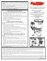
Page 30: ...MID TECH 6000 6100 OR 6200 CONTROL SYSTEM ...

Page 31: ...LEGACY 6000 SYSTEM ...

Page 32: ......

Page 33: ......

Page 34: ......

Page 35: ...Ag Leader Technology DirectCommand Installation DirectCommand 3 Channel Spreader Kit Page 4 of 15 December 2009 PN 2005689 Rev D Component and Cable Layout ...

Page 36: ...Optional Equipment ...

Page 37: ...03 flat washer various 6 N 16 0900 3 8 x 9 bolt 8 or 10 7 S 1 _ _ _ full SS cover sheet 1 Note these items may be different for each body please specify when ordering Body Extension Brackets Body Extension Brackets Ref Part Description Qty 1 S 1 45A corner ext bracket 4 ns S 1 45B side ext bracket 2 Note please specify what size extension boards you are using when ordering these parts ...

Page 38: ...s side tarp arm 1 6 SY 12 23B crank coupler 1 ns D 1 114 set screw 2 ns R 3 28 key 1 note parts are specific to size of body Ref Part Description Qty 1 S 12 29 bearing mount 1 2 S 12 28 Z mounting bracket 2 3 S 12 33 pass Side tarp arm 1 4 S 12 22 tarp 11 body 1 4 S 12 20A tarp 13 body 1 5 R 2 6 bearing 1 ns S 12 35 front tarp pipe 1 note parts are specific to size of body Ref Part Description Qty...

Page 39: ...23M motor mount 1 Body Tie Down Assembly NEW Ref Part Description Qty 1 S 1 1 Upper Bracket 4 2 SY 1 1 Spacer 4 3 T 1 16A Spring Guide 2 4 T 1 16 Spring 2 5 S 1 2 Lower Bracket 4 6 N 112 0002 Washer 4 7 N 112 0001A Lock Nut 4 8 N 112 0250 Bolt 4 NS N 110 0004 Lock Nut 8 NS N 110 0200 bolt 8 ...

Page 40: ...2 2 coupling 1 6 GP 82 6 2 x bushing 1 7 F 93 x 90 hose barb 1 8 F 18 hose clamp 1 9 F 80 hose per foot ns GP 180 5 1 x bushing 1 Foam Valve Assembly Ref Part Description Qty 1 S 11 5 solenoid valve 1 2 S 11 13 regulating valve 1 3 F 2 rubber hose per foot 4 F 17 hose clamp 2 5 F 42 x hose barb 2 6 GI 485 st elbow 2 7 S 6 151 hex nipple 1 ...

Page 41: ... body 1 5 F 94 x 90 hose barb 2 6 F 96 sight tube per foot 7 B 212 foam tank 1 ns GS 144 plug 1 ns F 42 x hose barb 1 ns H 181 ss check valve 1 Foam Marker Top View Ref Part Description Qty 1 F 80 hose per foot 2 F 18 hose clamp 1 3 F 93 x 90 hose barb 1 4 E 108 2 part A 1 5 E 122 2 cap 1 6 L 48 s hook 2 7 L 49 sash chain per foot ...

Page 42: ...________________________________________________ ______________________________________________________ ______________________________________________________ ______________________________________________________ ______________________________________________________ ______________________________________________________ ______________________________________________________ _____________________...

Page 43: ...RS MANUAL LIMITED WARRANTY AND REMIDIES General Fertilizer Equipment INC warrants each of its products for a period of 90 day from the date of purchase by the original customer end user under normal use and service This warranty provides that all products are free of defective materials and workmanship however it is limited to the replacement of any parts or the allowance of credit thereof which w...

Page 44: ......

Reviews: