IQ lock AUT, EL / EL DL, EM / EM DL, C / C DL, M / M DL
39
Installation
4.7 Sliding door fittings
The sliding door fittings that are listed in the approval in accordance with DIN EN 179 and 1125 may be combined
with the GEZE self-locking panic locks.
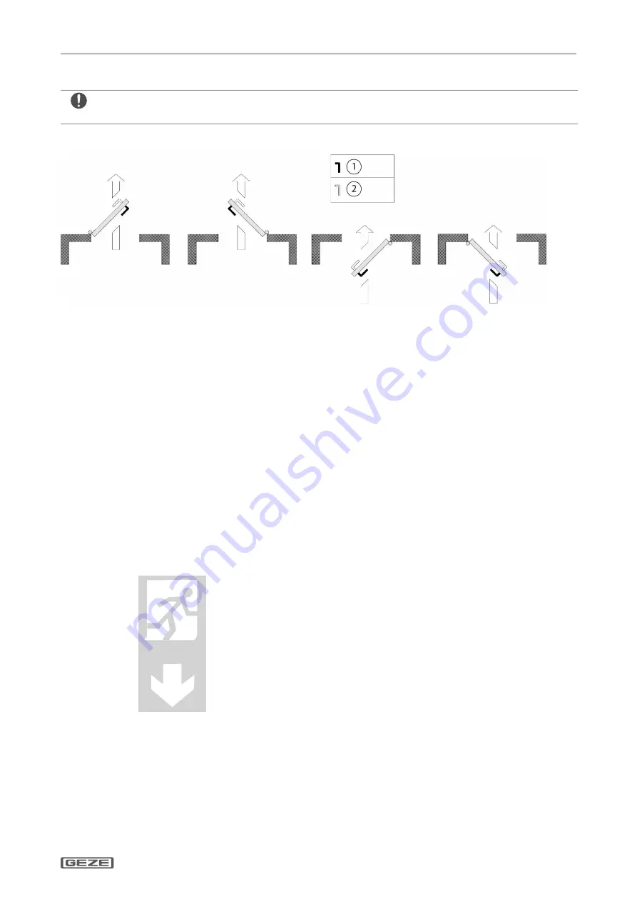
Stop direction for lever lock IQ lock EM/IQ lock EM DL
Outward
-opening:
DIN
right
Outward
-opening:
DIN
left
Inward
*-opening:
DIN
right
Install IQ lock EM DIN left
Inward
*-opening:
DIN
left
Install IQ lock EM DIN right
1
Permanently engaged door handle
2
Electronically engageable door handle
* Subject to approval in connection with emergency exits
4.8 Function checks after installation of the mechanical components
After mounting, the following functions or installation states have to be ensured:
à
The door seals used must not have a negative influence on the proper function of the panic exit device.
X
Ensure that the door can be opened freely when the panic exit device is operated.
à
In the case of doors that cannot be opened wider than 90° a Class 2 panic exit device (normal projection) has
to be used.
à
Check whether glass elements at panic exit devices are equipped with safety glass or laminated safety glass.
à
Panic exit devices are not designed for use on double action doors.
X
Check whether all the planned keepers (closing recess, etc.) or claddings are installed. Compliance with DIN EN 179
or DIN EN 1125 must be guaranteed.
X
Check whether a sign with the text “Press against bar to open” or a pictogram (see illustration below) is at-
tached to the inside of the door immediately above the horizontal bar or on the bar itself, providing there is a
sufficiently large and level surface available for the required text.
à
The area of the pictogram should be at least 8,000 mm². The colours should be white on a green background.
à
After installation the arrow must point to the operating element.


