background image

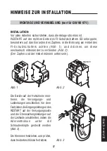
D
E
U

T
S

C
H

55

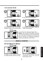
- Bei dauerndem Defekt

I

230V

INSERIRE CON

LEVA IN

POSIZIONE 

I

ON

OFF

TEST

I

0

230V

INSERIRE CON

LEVA IN

POSIZIONE 

I

ON

OFF

TEST

0

0

230V

INSERIRE CON

LEVA IN

POSIZIONE 

I

ON

OFF

TEST

0

230V

INSERIRE CON

LEVA IN

POSIZIONE 

I

ON

OFF

0

0

230V

INSERIRE CON

LEVA IN

POSIZIONE 

I

ON

OFF

TEST

0

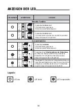
1. Normale Funktion

2. Ansprechen des FI-Schutzschalters.

3.  Das Gerät führt für min. 20 s eine Über-
prüfung der Anlage aus (rote Leuchte blinkt).

5. Zum Trennen der Anlage die Klappe öffnen. 
Hinweis:  Eine manuelle Rückstellung versuchen,
indem die Klappe geöffnet und der Hebel angehoben
wird. Falls keine erneute Aktivierung erfolgt, keine
weiteren Versuche zur Rückstellung durchführen,
sondern einen Elektriker zu Rate ziehen.

4. Rückstellung wird wegen Probleme der
Anlage nicht ausgeführt.

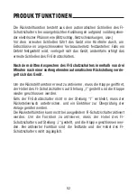
VON AUTOMATIK AUF MANUELL

MANUELLE FUNKTION

230V

INSERIRE CON

LEVA IN

POSIZIONE 

I

ON

OFF

I

Die Klappe bis zum hörbaren Einrasten
verschieben (Anlage mit Strom versorgt).

Fall die Stromversorgung der Anlage
unterbrochen werden soll, muss der
Hebel gesenkt werden.

230V

INSERIRE CON

LEVA IN

POSIZIONE 

I

ON

OFF

0

Click!

Click!

*

Summary of Contents for RESTART RD GW 90 971

Page 1: ...RESTART RD Serie 90 GW 90 971...

Page 2: ...ge un controllo dell impianto in seguito ad apertura dell interruttore differenziale per verificare la possibilit di ripristino automatico in sicurezza Eventuali posizioni intermedie della leva dell i...

Page 3: ...Funzionamento automatico 6 Inserimento modalit automatica 6 Riarmo automatico 6 Funzionamento manuale 7 Da automatico a manuale 7 Segnalazione dei led 8 Istruzioni per l installazione 9 Montaggio e ca...

Page 4: ...ale entro tre minuti da un precedente riarmo automatico il dispositivo si porta in stato di blocco Per riabilitare la funzione di riarmo aprire lo sportello alzare la leva del l interruttore differenz...

Page 5: ...PRODOTTO Leva di riarmo Alimentazione Sinottico Led di segnalazione Led di segnalazione Sportello in posizione di funzionamento automatico Terminali di verifica impianto Alimentazione Sportello in po...

Page 6: ...FF TEST 0 1 Funzionamento normale 2 Intervento dell interruttore differenziale 0 230V INSERIRE CON LEVA IN POSIZIONE I ON OFF TEST 0 I 230V INSERIRE CON LEVA IN POSIZIONE I ON OFF TEST I 3 L apparecch...

Page 7: ...20sec Spia rossa lampeggiante 5 Per sezionare l impianto aprire lo sportello Nota procedere ad un tentativo di riarmo manuale aprendo lo sportello ed alzando la leva In caso di mancata riattivazione...

Page 8: ...le scattato o aperto intenzionalmente Impianto non alimentato e sezionato Dispositivo di riarmo inserito Interruttore differenziale chiuso Impianto alimentato Dispositivo di riarmo in blocco per rilev...

Page 9: ...l foro della maniglia dell interruttore differenziale Fig 1 spingere per agganciarli meccanicamente fra loro Fig 2 Il perno e la maniglia devono essere gi Installare gli apparecchi sulla rotaia e coll...

Page 10: ...ssa in servizio far scattare l interruttore differenziale con le apposite strumentazioni di verifica impianto ed il dispositivo in funzionamento automatico Nel caso il ciclo di riarmo non venga conclu...

Page 11: ...CARATTERISTICHE TECNICHE SCHEMI D INSTALLAZIONE RD Alimentazione dall alto RD Alimentazione dal basso Id LOAD kWh LINE RD Id LOAD kWh RD LINE 11 I T A L I A N O Impianto utente Impianto utente...

Page 12: ...armo 2 minuti Intervallo minimo tra due chiusure consecutive 3 minuti Tensione di isolamento verso massa 2500V Potenza assorbita con interruttore differenziale chiuso 0 VA Potenza assorbita con RESTAR...

Page 13: ...E N G L I S H Series 90 RESTART RD...

Page 14: ...ce is in automatic mode it makes a check of the system following the opening of the differential switch to verify the possibility of restarting automatically in safety Possible intermediate positions...

Page 15: ...ructions 18 Automatic operation 18 Cutting in automatic mode 18 Automatic restart 18 Manual operation 19 From automatic to manual 19 Led signals 20 Installation instructions 21 Assembly and cabling on...

Page 16: ...ferential switch within three minutes of a previous automatic reset the device goes into locked status To re enable the restart function open the hatch raise the differential switch lever to position...

Page 17: ...G L I S H PRODUCT DESCRIPTION Reset lever Power supply Synoptic signal LED Signal LED Hatch in the automatic operation position System checking terminals Power supply Hatch in the manual operation po...

Page 18: ...OFF TEST 0 1 Normal operation 2 Differential switch cut in 0 230V INSERIRE CON LEVA IN POSIZIONE I ON OFF TEST 0 I 230V INSERIRE CON LEVA IN POSIZIONE I ON OFF TEST I 3 The device performs a test of t...

Page 19: ...erforms a test of the system of at least 20sec Red indicator blinking 5 Open the hatch to section the system Note attempt a manual reset by opening the hatch and raising the lever If the reset fails s...

Page 20: ...ch tripped or opened intentionally System disconnected and sectioned Restart device cut in Differential switch closed System powered up Restart device blocked due to a fault in the system down stream...

Page 21: ...to the hole in the differential switch handle Fig 1 push to couple them together mechanically Fig 2 The pin and the handle must be down Install the appliances on the rail and connect the line and load...

Page 22: ...tion I Fig 4 At the first start up trip the differential switch with the special system checking instrumentation and the device in automatic mode If the reset cycle is not concluded correctly check th...

Page 23: ...23 E N G L I S H TECHNICAL DATA INSTALLATION DIAGRAMS RD Power supply from above RD Power supply from below Id LOAD kWh LINE RD Id LOAD kWh RD LINE User s system User s system...

Page 24: ...on 2 minutes Minimum interval between two consecutive closings 3 minutes Insulation voltage towards earth 2500V Power absorbed with the differential switch closed 0 VA Power absorbed with RESTART bloc...

Page 25: ...F R A N A I S S rie 90 RESTART RD...

Page 26: ...nement et en cas d ouverture de l interrupteur diff rentiel un contr le de l installation afin de v rifier que le r arme ment automatique puisse s effectuer en conditions de s curit D ventuelles posit...

Page 27: ...tionnement automatique 30 Activation mode automatique 30 R armement automatique 30 Fonctionnement manuel 31 D automatique manuel 31 Signalisation des leds 32 Instructions pour l installation 33 Montag...

Page 28: ...lle de trois minutes apr s un r armement automatique le dispositif se place en tat d arr t Pour r activer la fonction de r armement ouvrir le volet soulever le levier de l interrupteur diff rentiel en...

Page 29: ...PRODUIT Levier de r armement Alimentation Synoptique LED de signalisation LED de signalisation Volet en position de fonctionnement automatique Bornes de contr le installation Alimentation Volet en po...

Page 30: ...EST 0 1 Fonctionnement normal 2 Intervention de l interrupteur diff rentiel 0 230V INSERIRE CON LEVA IN POSIZIONE I ON OFF TEST 0 I 230V INSERIRE CON LEVA IN POSIZIONE I ON OFF TEST I 3 Le dispositif...

Page 31: ...d au moins 20 s LED rouge clignotante 5 Pour sectionner l installation ouvrir le volet Remarque effectuer une tentative de r armement manuel en ouvrant le volet et en soulevant le levier Si le r armem...

Page 32: ...uvert intentionnellement Installation non aliment e et sectionn e Dispositif de r armement activ Interrupteur diff rentiel ferm Installation aliment e Dispositif de r armement en arr t pour d tection...

Page 33: ...nterrupteur diff rentiel Fig 1 Pousser pour enclencher m caniquement entre eux les dispositifs Fig 2 L axe et la poign e doivent tre en position basse Installer les dispositifs sur le rail puis branch...

Page 34: ...e en servi ce faire d clencher l interrupteur diff rentiel avec les instruments de contr le installation pr vus cet effet et avec le dispositif en fonctionnement automatique Si le cycle de r armement...

Page 35: ...I S 35 CARACT RISTIQUES TECHNIQUES SCH MAS D INSTALLATION RD Alimentation depuis le haut RD Alimentation depuis le bas Id LOAD kWh LINE RD Id LOAD kWh RD LINE Installation utilisateur Installation ut...

Page 36: ...es Intervalle minimum entre deux fermetures cons cutives 3 minutes Tension d isolation vers la masse 2500V Puissance absorb e avec l interrupteur diff rentiel ferm 0 VA Puissance absorb e avec RESTART...

Page 37: ...E S P A O L Serie 90 RESTART RD...

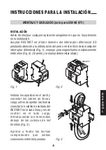
Page 38: ...desarrolla un control de la instalaci n despu s de la apertura del interruptor dife rencial para comprobar la posibilidad de reajuste autom tico en seguridad Posibles posiciones intermedias de la pala...

Page 39: ...onamiento autom tico 42 Introducci n modalidad autom tica 42 Rearme autom tico 42 Funcionamiento manual 43 De autom tico a manual 43 Se alizaci n de los led 44 Instrucciones para la instalaci n 45 Mon...

Page 40: ...ntes de tres minutos de un precedente rearme autom tico el dispositivo se lleva a estado de bloqueo Para rehabilitar la funci n de rearme abrir la ventanilla levantar la palan ca del interruptor difer...

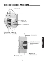
Page 41: ...DUCTO Palanca de rearme Alimentaci n Sin ptico Led de se alizaci n Led de se alizaci n Ventanilla en posici n de funcionamiento autom tico Terminales de control instalaci n Alimentaci n Ventanilla en...

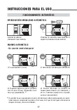
Page 42: ...Funcionamiento normal 2 Intervenci n del interruptor diferencial 0 230V INSERIRE CON LEVA IN POSIZIONE I ON OFF TEST 0 I 230V INSERIRE CON LEVA IN POSIZIONE I ON OFF TEST I 3 El aparato realiza un tes...

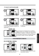
Page 43: ...Dispositivo luminoso rojo parpadeante 5 Para seccionar la instalaci n abrir la ventanilla Nota proceder con un tentativo de rearme manual abriendo la ventanilla y levantando la palanca En caso de falt...

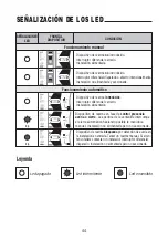
Page 44: ...sparado o abierto intencionalmente Instalaci n no alimentada y seccionada Dispositivo de rearme introducido Interruptor diferencial cerrado Instalaci n alimentada Dispositivo de rearme bloqueado por d...

Page 45: ...nija del interruptor diferencial Fig 1 empujar para engancharlos mec nicamente entre ellos Fig 2 El perno y la manija deben estar abajo Instalar los aparatos en el carril y conectar los cables de l ne...

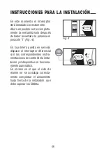
Page 46: ...ta en servicio disparar el interruptor diferencial con las correspondientes instru mentaciones de control de la insta laci n yel dispositivo en funciona miento autom tico En el caso en el que el ciclo...

Page 47: ...E S P A O L 47 CARACTER STICAS T CNICAS ESQUEMAS DE INSTALACI N RD Alimentaci n desde arriba RD Alimentaci n desde abajo Id LOAD kWh LINE RD Id LOAD kWh RD LINE Instalaci n usuario Instalaci n usuario...

Page 48: ...me 2 minutos Intervalo m nimo entre dos cierres consecutivos 3 minutos Tensi n de aislamiento hacia masa 2500V Potencia absorbida con interruptor diferencial cerrado 0 VA Potencia absorbida en RESTART...

Page 49: ...D E U T S C H Serie 90 RESTART RD...

Page 50: ...einer Ausl sung des FI Schutzschalters eine berpr fung der Elektroanlage um die M glichkeit einer sicheren R ckstellung zu pr fen Eventuelle Zwischenstellungen des Schalterhebels stellen solange sie v...

Page 51: ...g 54 Automatikfunktion 54 Automatische aktivierung 54 Automatische r ckstellung 54 Manuelle funktion 55 Von automatik auf manuell 55 Anzeigen der led 56 Hinweise zur installation 57 Montage und verkab...

Page 52: ...on drei Minuten nach einer vorhergehenden automatischen R ckstellung verrie gelt sich das Ger t Um die R ckstellfunktion erneut zu aktivieren muss die Klappe ge ffnet der Hebel des FI Schutzschalters...

Page 53: ...H 53 PRODUKTBESCHREIBUNG R ckstellhebel Stromversorgung Synoptisches Anzeige led Anzeige led Klappe in Stellung Automatikfunktion Klemmen zur Anlagenpr fung Stromversorgung Klappe in Stellung manuell...

Page 54: ...T 0 1 Normale Funktion 2 Ansprechen des FI Schutzschalters 0 230V INSERIRE CON LEVA IN POSIZIONE I ON OFF TEST 0 I 230V INSERIRE CON LEVA IN POSIZIONE I ON OFF TEST I 3 Das Ger t f hrt f r ca 60 s ein...

Page 55: ...ennen der Anlage die Klappe ffnen Hinweis Eine manuelle R ckstellung versuchen indem die Klappe ge ffnet und der Hebel angehoben wird Falls keine erneute Aktivierung erfolgt keine weiteren Versuche zu...

Page 56: ...el st oder absichtlich geschaltet Anlage nicht gespeist und getrennt R ckstellger t aktiviert FI Schutzschalter geschlossen Stromversorgung Elektroanlage ein R ckstellger t f r berpr fung der nachgesc...

Page 57: ...Abb 1 und dr cken um diese mechanisch miteinander zu verbinden Abb 2 Der Zapfen und der Hebel m ssen unten sein Die Ger te auf der Hutschiene mon tieren die Versorgungs und Lastleitungen anschlie en...

Page 58: ...werden Bei der ersten Inbetriebnahme muss der FI Schutzschalter in automatischem Betrieb zum Ausl sen gebracht werden Falls der R ckstellzyklus nicht kor rekt abgeschlossen wird muss die Isolierung d...

Page 59: ...D E U T S C H 59 TECHNISCHE EIGENSCHAFTEN INSTALLATIONSDIAGRAMME RD Anschluss von oben RD Anschluss von unten Id LOAD kWh LINE RD Id LOAD kWh RD LINE Anwenderanlage Anwenderanlage...

Page 60: ...Minuten Mindestabstand zwischen zwei aufeinander folgende Ausl sungen 3 Minuten Isolierspannung f r Erde 2500 V Aufgenommene Leistung bei geschlossenem FI Schutzschalter 0 VA Aufgenommene Leistung mit...

Page 61: ...61 NOTE...

Page 62: ...62 NOTE...

Page 63: ......

Page 64: ...39 035 946 111 8 30 12 30 14 00 18 00 da luned a venerd 39 035 946 260 24 ore al giorno SAT on line gewiss gewiss com SAT MATERIALE ELETTRICO COD 7 42 5 451 7 ULTIMA REVISIONE 08 2005...

Reviews: