background image

26

regulations of the employer‘s liability insur-
ance association. Discuss the details with 
the specialist planner or specialist compa-
ny responsible during the planning phase.

Intended use

The product is designed to control de-
centralised ventilation units in residential 
buildings. Use of the product is permitted 
only in conjunction with the components 
recommended by the manufacturer. Mod-
ifications to the product or system are 
prohibited.

Improper use

Any other use is considered improper. 
Resulting damages are excluded from 
liability.

2 Function

The control unit connects several decen-
tralised ventilation units and regulates 
the home ventilation system as a whole. 
It allows you to adjust various functions, 
such as heat recovery or ventilation. It can 
control the speed of the fans according 
to your requirements. It also indicates 
upcoming filter replacement intervals for 
the unit.

2.1 Use

Prerequisites for trouble-free and safe 
product operation are: correct transport 
and storage; professional planning and 
installation; and careful operation and 
maintenance.
Create a project plan prior to starting work. 
This should define both the number and 
location of ventilation units and associ-
ated control units, as well as the ventila-
tion principle (cross ventilation, individual 
room ventilation, extraction).
During planning, installation and opera-
tion, observe the approval requirements 
and applicable building regulations, and 
the fire protection and accident prevention 

Summary of Contents for TOUCH

Page 1: ...MONTAGE BEDIENUNGSANLEITUNG INSTALLATION USER GUIDE DEEN 190128 01 TO 50007177 TOUCH MENU ECO MODUS ...

Page 2: ...laubt und nicht genehmigungspflichtig Technische Änderungen vorbehalten Keine Haftung für Druckfehler All information contained in these documents is the property of the manufacturer Any publishing thereof whether in part or in whole requires a written consent Copying the instructions within the same company for the purpose of evaluating the product or for other product related uses is permitted a...

Page 3: ...on 8 4 1 Montage 9 4 2 Steckerverbindung 11 4 3 DIP Schalter 12 5 Bedienung 13 5 1 Einrichtung 13 5 2 Anzeige Bedienelemente 14 5 3 Modi Funktionen 15 5 4 Konfiguration der Modi 17 5 5 Filterwechsel 18 5 6 Sensor Einheit 18 6 Störungsbehebung 19 7 Wartung 19 8 Umwelt und Entsorgung 19 9 Gewährleistung 20 10 Haftung 21 11 Anhang Attachment 42 ...

Page 4: ...G Vor Gebrauch sorgfältig lesen Aufbewahren für späteres Nachschlagen Überprüfen Sie die Lieferung bei Erhalt anhand des Lieferscheines auf Vollständigkeit und Transportschäden Reklamieren Sie fehlende Positionen innerhalb von vier Wochen bei Ihrem Lieferanten Die Produkte dürfen nicht im Freien gelagert werden Sie müssen trocken frost und staubfrei eingelagert sowie vor aggressiven Medien und Son...

Page 5: ...ingehalten werden Bei Nichtbeachten können Sachschäden und Personenschäden bis hin zur Lebensgefahr entstehen Vor der Installation den Strom ab schalten In einigen Ländern dürfen Elektroinstallationen nur von autori sierten Elektrofachleuten ausgeführt werden Im Zweifelsfall die örtlichen Behörden ansprechen Alle Kleinspannungskabel von Netzspannung führenden Kabeln getrennt verlegen Mindestabstan...

Page 6: ...usgeschlossen 2 Funktion Die Steuerung verbindet mehrere dezen trale Lüftungsgeräte und kontrolliert das gesamte Wohnraumlüftungssystems Es lassen sich verschiedene Funktionen wie zum Beispiel die Wärmerückgewinnung oder das Durchlüften einstellen Je nach Bedarf kann die Drehzahl der Lüfter ge steuert werden Darüber hinaus zeigt das Gerät anstehende Filterwechselintervalle an 2 1 Verwendung Voraus...

Page 7: ...7 3 Abmessungen 3 2 1 5 Ø 54 4 1 Bedieneinheit 2 Rahmen 3 Basis 4 Unterputz Netzteil 5 Hutschienen Netzteil ...

Page 8: ...on 1 Netzanschluss 230 V AC 2 Netzteil 3 Lüfter Anschlussreihe 2 4 Basis 5 Lüfter Anschlussreihe 1 42 V GND GND 42 V 42 V Bus A Bus B GND GND 42 V 42 V Bus A Bus B GND 42 V Bus A Bus B GND 42 V Bus A Bus B 2 1 4 3 5 ...

Page 9: ...sternverka belten Lüftern Querschnitt Lüfter Segmentlänge LS Unterputz 26 4 W Hutschiene 30 W Reihen verkabelung Stern verkabelung Reihen verkabelung Stern verkabelung 0 25 mm 2 30 m 30 m 30 m 50 m 4 20 m 20 m 20 m 25 m 6 10 m 0 5 mm 2 45 m 45 m 45 m 60 m 4 30 m 30 m 30 m 40 m 6 15 m 20 m 0 75 mm 2 60 m 60 m 60 m 75 m 4 40 m 40 m 40 m 50 m 6 10 m 20 m 25 m Ls Ls Abhängig vom verwendeten Netzteil u...

Page 10: ...eschädigung der elektrischen Komponenten Nach Unterbrechung der Stromversorgung hält das Netzteil die Ausgangsspannung für einen kleinen Zeitraum aufrecht Durch falsche Belegung der Anschlüsse an der Basis können die elektrischen Komponenten der Lüfter und Steuerung beschädigt werden Anschluss an der Basis und Steckerbele gung entsprechend Schaltplan durchführen und sorgfältig prüfen Unterputz Net...

Page 11: ...in die Basis einstecken 9 Hutschienen Netzteil auf der Hutschie ne im Verteilerkasten montieren 10 Netzkabel an Netzteil anschließen 4 2 Steckerverbindung Damit der Lüfter für die Wartung einfach von der Anschlussleitung getrennt wer den kann wird ein Steckverbinder an das 8 Netzteil in der Unterputzdose platzieren 9 Basis in der Unterputzdose befestigen 10 Bedieneinheit und Rahmen in die Basis ei...

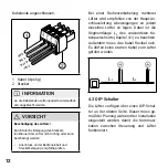
Page 12: ...r verfügen über einen DIP Schal ter an der oberen Seite Dieser muss ge mäß der Planung während der Installation eingestellt werden damit die Kommuni kation zwischen Steuerung und Lüfter funktioniert Kabelende angeschlossen GND Bus A Bus B 42 V 2 1 1 Kabel 4 polig 2 Stecker INFORMATION An die Kabelenden sollen isolierte Aderendhül sen angebracht werden VORSICHT Beschädigung des Lüfters Durch falsch...

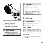
Page 13: ...tivität muss etwas fester gedrückt werden 5 1 Einrichtung Nach der Installation oder dem Zurückset zen auf die Werkseinstellungen muss die Steuerung beim ersten Start eingerichtet werden Die Einrichtung wird wie folgt durchgeführt 1 START drücken um die Einrichtung zu beginnen 2 Systemsprache auswählen 2 1 1 Schalter 1 3 Zone 1 3 Oben AN Unten AUS 2 Schalter 4 Startrichtung Oben Abluft Unten Zuluf...

Page 14: ...uswahl 1 2 3 oder Alle 6 Menü 7 Lüfterstufe herunterschalten 8 Lüfterstufe heraufschalten 3 Aktuelle Uhrzeit in Stunden und Minu ten einstellen 4 Räume in Zone 1 definieren 5 Falls vorhanden Zone 2 siehe DIP Schalter aktivieren und Räume der Zone 2 zuordnen 6 Falls vorhanden Zone 3 siehe DIP Schalter aktivieren und Räume der Zone 3 zuordnen 7 Die Einrichtung ist nun abgeschlossen und das System ka...

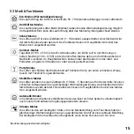
Page 15: ...Icon die Start und Endzeiten um jeweils 3 Stunden vor oder zurück gestellt werden Party Modus Die Lüfter durchlüften die Wohneinheit auf höchster Stufe um einen schnellen Luftaus tausch mit Frischluft zu gewährleisten Stoßlüften Modus Die Lüfter pendeln in einem Zeitbereich 15 Min 5 Stunden auf höchster Stufe für einen schnellen Luftaustausch bei gleichzeitiger Wärmerückgewinnung Anschließend wird...

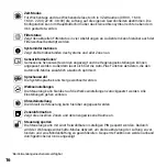
Page 16: ...n Außerdem lässt sich hier die Auto Plus Funktion aktivieren die den Automatik Modus zusätzlich akustisch optimiert Sprachauswahl Die Systemsprache kann hier gewechselt werden Werkseinstellungen Die Steuerung kann hierüber auf die Werkseinstellungen zurückgesetzt werden Alle Einstellungen gehen verloren Uhrzeiteinstellung Die Uhrzeit der Steuerung kann hierüber angepasst werden Zoneninformation Ze...

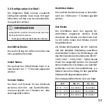
Page 17: ... gewählten Zeitabschnitt abgeschaltet werden Die voreingestellten Werte sind wie folgt Zeit Mo Fr Sa So 08 00 16 00 Eco Stufe 2 Eco Stufe 2 16 00 22 00 Eco Stufe 1 Eco Stufe 1 22 00 08 00 Eco Stufe 1 Eco Stufe 1 5 4 Konfiguration der Modi Die folgenden Modi können zusätzlich konfiguriert werden Dazu muss im Haupt bildschirm auf das Icon des aktuellen Mo dus gedrückt werden INFORMATION Aufgrund des...

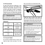
Page 18: ...g der Umge bungsparameter durchgeführt 5 5 Filterwechsel Die Steuerung bestimmt abhängig von der geförderten Luftmenge den Zeitpunkt des nächsten Filterwechsels Sobald ein Filter wechsel notwendig ist blinkt im Hauptbild schirm das Filterstatus Icon auf Im Menü Filterstatus kann der Filterwechsel bestätigt werden und das Intervall wird zurückgesetzt INFORMATION Die optimale Zeit bis zum Filterwech...

Page 19: ...prüfen lassen Filterstatus Icon blinkt regelmä ßig auf Filterwechselzeitpunkt erreicht Filter prüfen und ggf austauschen Im Menü über das Filterstatus Icon den Filterwechsel bestätigen Touchscreen reagiert träge Das resistive Display reagiert auf präzisen Druck Position des Druckpunktes leicht verändern Hilfsmittel wie z B einen Eingabestift verwenden Einzelne Modi sind gesperrt Die Steuerung wurd...

Page 20: ...erung falls Der Gewährleistungszeitraum abgelaufen ist Der Kaufnachweis bei der Servicean frage nicht vorgelegt werden kann Wiederverwertung zugeführt werden Eine separate Entsorgung des Produkts trägt zur Minderung des Verbrennungs oder Depo nieabfalls bei und reduziert die Belastung der menschlichen Gesundheit und Umwelt Verpackungsmaterialien sind sortenrein zu entsorgen 9 Gewährleistung INFORM...

Page 21: ...rschleiß Das Problem durch unsachgemäße harte oder unachtsame Behandlung Verwendung bzw Wartung verur sacht wurde Das Produkt mit Bau oder Ersatztei len die nicht vom Hersteller geliefert oder freigegeben wurden betrieben wurde Nicht genehmigte Änderungen oder Modifikationen am Produkt vorge nommen wurden Das Problem durch Feuer oder eine andere Naturkatastrophe verursacht wurde Das Problem durch ...

Page 22: ......
Page 23: ...allation 28 4 1 Montage 29 4 2 Connection 32 4 3 DIP switch 32 5 Operation 33 5 1 Setup 33 5 2 Display programming unit 34 5 3 Modes functions 35 5 4 Modes configuration 37 5 5 Filter replacement 38 5 6 Sensor unit 38 6 Troubleshooting 39 7 Maintenance 39 8 Environment disposal 39 9 Warranty 40 10 Liability 41 11 Anhang Attachment 42 ...

Page 24: ...On receipt check your shipment against the delivery note for com pleteness and any damage sustained during transport Report any missing items to your supplier within four weeks Never store these products outdoors Store them somewhere dry and protected from frost dust corrosive media and direct sunlight Make sure that the relative humidity at the stor age location is no higher than 60 In addition t...

Page 25: ... can result in property damage injury and even death Switch off the power supply prior to installation In some countries only authorised electricians may carry out electrical installations If in doubt contact the local authorities Lay all low voltage cables separately from main voltage cables minimum distance 100 mm Children aged 8 years and above and people with impaired physical sensory or menta...

Page 26: ...he home ventilation system as a whole It allows you to adjust various functions such as heat recovery or ventilation It can control the speed of the fans according to your requirements It also indicates upcoming filter replacement intervals for the unit 2 1 Use Prerequisites for trouble free and safe product operation are correct transport and storage professional planning and installation and car...

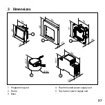
Page 27: ...27 1 Programming unit 2 Frame 3 Base 4 Flush mounted power supply unit 5 Top hat rail power supply unit 3 2 1 5 Ø 54 4 3 Dimensions ...

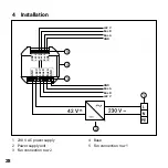
Page 28: ...ower supply 2 Power supply unit 3 Fan connection row 2 4 Base 5 Fan connection row 1 42 V GND GND 42 V 42 V Bus A Bus B GND GND 42 V 42 V Bus A Bus B GND 42 V Bus A Bus B GND 42 V Bus A Bus B 2 1 4 3 5 4 Installation ...

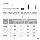
Page 29: ...d star connected fans Cross section Fans Segment length LS Flush mounted 26 4 W Top hat rail 30 W Series connection Star connection Series connection Star connection 0 25 mm 2 30 m 30 m 30 m 50 m 4 20 m 20 m 20 m 25 m 6 10 m 0 5 mm 2 45 m 45 m 45 m 60 m 4 30 m 30 m 30 m 40 m 6 15 m 20 m 0 75 mm 2 60 m 60 m 60 m 75 m 4 40 m 40 m 40 m 50 m 6 10 m 20 m 25 m Ls Ls Up to 6 fans can be used depending on...

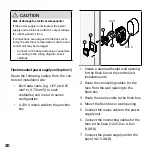
Page 30: ... base 42 V GND CAUTION Risk of damage to electrical components If the power supply is interrupted the power supply unit remains live with the output voltage for a brief period of time If connections are assigned to the base incor rectly the electrical components of the fan and control unit may be damaged Connect to the base and assign connectors according to the wiring diagram check carefully Flus...

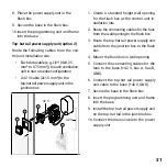
Page 31: ...re the base in the flush box 8 Insert the programming unit and frame into the base 9 Install the top hat rail power supply unit on the top hat rail in the junction box 10 Connect the mains cable to the power supply unit 8 Place the power supply unit in the flush box 9 Secure the base in the flush box 10 Insert the programming unit and frame into the base Top hat rail power supply unit option 2 Rou...

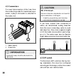
Page 32: ...ross section used chap ter 4 1 The cable must also be flexible Rigid cables must not be routed to the fan Ls Ls 4 3 DIP switch The fans have a DIP switch on the top Dur ing installation this must be configured according to the design so that the control unit and fans can communicate 4 2 Connection For easy disconnection of the fans from the connecting cable for maintenance pur poses a plug in conn...

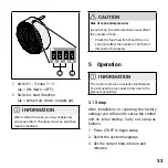
Page 33: ...te firmly due to the pressure sensitivity 5 1 Setup After installation or restoring the factory settings you will need to set up the control unit on initial startup Carry out setup as follows 1 Press START to begin setup 2 Select the system language 3 Set the current time in hours and minutes 2 1 1 Switch 1 3 zone 1 3 up ON down OFF 2 Switch 4 start direction up extract air down supply air INFORMA...

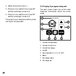
Page 34: ...e menu 2 Current mode icon 3 Current fan stage 4 On Off 5 Zone selection 1 2 3 or All 6 Menu 7 Fan stage down 8 Fan stage up 4 Define the rooms in zone 1 5 If there is one enable zone 2 see DIP switch and assign rooms to it 6 If there is one enable zone 3 see DIP switch and assign rooms to it The setup is now complete and the system can be put into operation ...

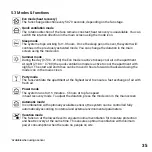
Page 35: ... the quick ventilation mode is active to cool the apartment with night air The start and end times can be moved 3 hours forward or backward using the mode icon in the main screen Party mode The fans ventilate the apartment at the highest level to ensure a fast exchange of air with fresh air Power mode The system runs for 15 minutes 5 hours at top fan speed in heat recovery mode To adjust the durat...

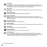
Page 36: ...s can be adjusted In addition the Auto Plus function can be activated here which also acoustically optimises the automatic mode Language selection The system language can be changed here Factory settings This can be used to reset the control unit to the factory settings All settings will be lost Time setting The time of the control unit can be adjusted here Zone information Displays the individual...

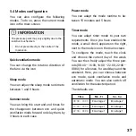
Page 37: ...ff ventilation for the selected period The defaults are Time Mo Fr Sa Su 08 00 16 00 Eco stage 2 Eco stage 2 16 00 22 00 Eco stage 1 Eco stage 1 22 00 08 00 Eco stage 1 Eco stage 1 5 4 Modes configuration You can also configure the following modes To do so press the current mode icon in the main screen INFORMATION The pressure point may vary slightly due to the resistive touchscreen Do not press d...

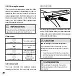
Page 38: ... 5 5 Filter replacement The control unit determines when the filter should be replaced depending on the re quired air flow rate As soon as a filter re quires replacement the filter status icon in the main screen flashes In the filter status menu you can confirm filter replacement and the interval will reset INFORMATION The optimum time until filter replacement can vary depending on local environme...

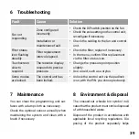
Page 39: ...k the cabling to the fan and control unit Filter status icon flashing steadily Filter replacement interval elapsed Check the filter replace if necessary In the menu confirm filter replacement via the filter status icon Touchscreen slow to respond The resistive display responds to precise pressure Change the pressure point position slightly Use an aid such as a stylus Some modes are locked The cont...

Page 40: ...ve operated the product with components or spare parts not supplied or approved by the manufacturer You have made unauthorised reduce incinerated and landfill waste vol umes and reduces the impact on environ mental and human health Sort packaging materials and dispose of them accordingly 9 Warranty INFORMATION Outside Germany national warranty conditions of the country in which the system is opera...

Page 41: ...idered improper and may result in product damage or personal injury for which the manufactur er cannot be held liable The manufacturer shall not be liable for any damage resulting from the following Failure to observe the safety operating and maintenance instructions speci fied in the documentation Non compliant installation Installation of spare parts not supplied or stipulated by the manufacture...

Page 42: ...ry CR 2032 Betriebstemperatur Operating temperature C 0 40 Eigenschaften Features Bedienung Operation Touchscreen Anzahl Modi Number of modes 8 Sensorik Sensors Optional Filterwechselanzeige Filter change indicator Display Abmessungen Dimensions Einbaumaße ØxT Installation dimensions ØxD mm 58 x 35 Bedienelement BxH Inside cover WxH mm 50 x 50 Rahmen BxH Frame WxH mm 80 x 80 Gewicht Weight kg 0 21...

Page 43: ...1 2 Verkabelungsprotokoll Wiring protocol Gerät Device Geschoss Floor Raum und Positionierung Room and Position Startrichtung Start direction Zuluft Supply air Abluft Exhaust air 1 2 3 4 5 6 7 8 9 10 11 12 ...

Page 44: ...getAir GmbH Krefelder Straße 670 41066 Mönchengladbach 49 2161 990 95 0 49 2161 990 95 99 service getair eu www getair eu M A D E I N G E R M A N Y ...

Reviews: