background image

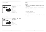
4. Chairman Unit 

Mic  Capsule:  to  pickup  vocal  & 

transfer to amplify.

 Mic Light Loop

 Display Windows

④ 

Up

 Enter

 Priority button

 On/Off button

 Power Switch

 Charging Jack: +6V

5.Delegate Unit

Mic  Capsule:  to  pickup  vocal  & 

transfer to amplify.

 Mic Light Loop

③ 

Display Windows

④  

Up

⑤  

Enter

 On/Off button

 Power Switch

 Charging Jack: +6V

Wireless Conference System

6. Menu

Unit Menu

Press “ENTER” to enter setup interface. Left side is for channel, right side 

is for unit address.

Press  “UP”  to  revise  the  value  of  flashing  data,  then  press  ENTER  to  set 

value.

 Press “ENTER” to exit setting after setup.

Main Controller Menu

Press “ENTER” to enter menu;

Press “UP”/ “DOWN” to move cursor;

Press “LEFT”/ “RIGHT” to revise value;

 Press “ESC” to save setup & exit;

There  are  three  option  for  setup:  Channel,  Screen  Freeze,  One  Key 

Shutdown.

② 


Wireless Conference System

Summary of Contents for EG-7230

Page 1: ...CAMERA TRACKING CONFERENCE SYSTEM WIRELESS 3 CHANNELS USER MANUAL ...

Page 2: ...e 0 40 The power cable plug must be put into the grounded socket Please don t operate where there is a sign of and leave it to the professional technician Please use the specified battery from our distributor The installation gap around this equipment shall be over 20cm Wireless Conference System 1 General Function 2 Front Pannel 3 Rear Pan 4 Chairman Unit 5 Delegate Unit 6 Menu 7 System Connectio...

Page 3: ...ith central controller 2 Front Pannel POWER Switch RIGHT DOWN LEFT ENTER UP ESC Display Wireless Conference System 3 Rear Pannel Audio channel UHF A B C receiving antenna connector BNC type USB port for audio recording 6 3 RCA audio output XLR audio output RS 232 port for PC Camera port for both RS485 RS232 communication When connecting RS485 camera connect RX to TXD of camera connect TX to RXD of...

Page 4: ...ing Jack 6V Wireless Conference System 6 Menu Unit Menu Press ENTER to enter setup interface Left side is for channel right side is for unit address Press UP to revise the value of flashing data then press ENTER to set value Press ENTER to exit setting after setup Main Controller Menu Press ENTER to enter menu Press UP DOWN to move cursor Press LEFT RIGHT to revise value Press ESC to save setup ex...

Page 5: ...to PA system To get the best communication the minimum installation height to the ground shall be 1m the minimum distance between launch antenna receiving antenna shall be 2m the minimum distance to wall shall be 1m Keep antennas away from interference such as computer digital equipment TV also big metal item Adjust volume on amplify mixer to the minimum before turning on microphone unit Remark Au...

Page 6: ...x Deviation Range Capsule RF output power Battery Current Working hours Dimension Weight Capacitive UMUnidirectional 3 7Li Battery 250mA About 7 hours 150 120 440mm 1kg 483 323 90mm 5 1kg Wireless Conference System 11 Camera Tracking Connect PC with main controller via RS 232 port Install the software from attached CD Enter software to find below login interface Select the serial port then click V...

Page 7: ...hannel before setup camera tracking Set preset point related to the unit ID There is a camera switch module in the system It supports maximum 4 cameras If more cameras are required the video switch device shall be connected to system Wireless Conference System ...

Reviews: