16
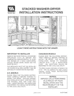
Examples of installation
NRG 16-50, NRG 17-50, NRG 19-50
Centre distance
Fig. 16
Inclined installation, e. g. in ascending inlet lines
of hot-water installations or vessels
Fig. 15
Protection tube (provided on site) if electrode is
used as internal water-level limiter
Fig. 17
Protection tube (provided on site) if electrode is
used as internal water level-limiter combined
with water level control or high water level
alarm
Fig. 18
Level pot ≥ DN 80 if electrode is used as
external water level limiter
g
h
i
j
k
g
h
k
j
i
g
j
p
l
o
p
o
m
n
o
p
DN 100
∅
20
20
≥ DN 20
24.5 24.5
20
∅
20
DN 50
G ¾
G¾
G¾
≥ 20
≤ 3000
∅
20
≤ 90°
∅
20
G¾
≤ 90°
≥14
≥ DN 20
≥ DN 20
max.
1000
20
≥14
≥14
45°
≥ 10
≥
10
≥10
n
190
≥ DN 80
Summary of Contents for NRG 111-50
Page 22: ...22 For your Notes ...
Page 23: ...23 For your Notes ...