22
NRG 10-52, NRG 16-52 - USA - Installation & Operating Manual -
850696-00
Connecting the level electrode
Use a shielded, multi-core TC-ER control cable with minimum wire size AWG18, e.g., OELFLEX
CONTROL TM CY 5G1, to connect the level electrode. Max. length 328 ft (100 m).
Connect the shield
just once
to the central grounding point
(CGP) in the control cabinet
.
Electrical connection
Assigning the five-pole connector of the NRG 10-52, NRG 16-52
■
Please pay attention to the Installation and Operating Manual of the NRS 1-56
level switch.
■
Route the connecting cables to the level electrode separately from power lines.
■
Check the connection of the shield to the central grounding point (CGP) in the
control cabinet.
Attention
1. Swing the retaining bracket
j
up and detach the upper part of the connector
o
from the
level electrode.
2. Undo the screw
m
and press the contact block
l
out of the upper part of the connector
o
.
Take care not to lose the sealing ring
n
.
3. Unscrew the cable gland
r
.
4. Pull the cable
s
through the cable gland
r
, ring
q
, gasket
p
and upper part of the connec-
tor
o
.
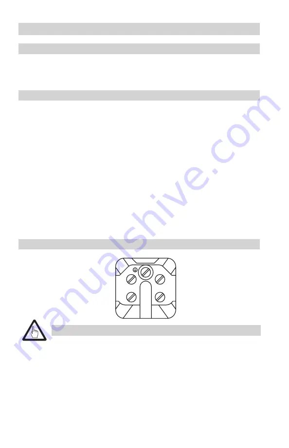
5. Connect the terminals (
Fig. 8
) in the contact block
l
according to the
Functions table on
page 17
.
6. Press the contact block
l
into the upper part of the connector
o
.
7. Insert the screw
m
in the hole once more (with sealing ring
n
) and tighten. This secures the
contact block
l
in the upper part of the connector
o
.
8. Tighten the cable gland
r
.
9. Insert the upper part of the connector
o
in the lower part
k
and fasten by swinging the
retaining bracket
j
down.
Terminals in the contact block
Fig. 8
4
3
1
2


