background image

S

M

A

 5

B

E

R

-

13

-

23

.G1

 /

 0

1.

05

.2

02

/ V

 0

1.

01

-

E

N

G


©


15


Settings (radius)


too large


Guiding roll too large 


(radius incomplete)


too small


Guiding roll too small 


(radius cuts into material)


> 90°


Angle greater than 90°


(radius incomplete)


< 90°


Angle smaller than 90° 


(radius cuts into material)


Notes on radius milling:


Choosing the right guiding roll to ensure the correct 

lateral position of the radius is just as important as 

setting the correct height of the guiding plate.


If the wrong guiding roll is used, the machined radi-

us will not form a smooth transition with the end 

face of the workpiece.


If the guiding roll used is too large, the appearance 

of the resulting radius is similar (but rotated by 90°) 

to that created when the guiding plate is set too low.


If the guiding roll used is too small, the appearance 

of the resulting radius is similar (but rotated by 90°) 

to that created when the guiding plate is set too 

high.


The same phenomenon arises if the end and upper 

faces of the workpiece are not aligned at right 

angles to one another.


If the edge of workpiece to be machined was crea-

ted by cutting with a plasma cutter, the upper and 

end faces of the workpiece may be out of rectangu-

lar alignment by as much as 7°. This type of misa-

lignment will result in a radius that is either incom-

plete or that cuts too far into the material depending 

on whether the upper or lower surface of the work-

piece is being machined.


Although our conically shaped gui-

ding rolls are designed to put up 

against the workpiece immediately 

below the carbide inserts and can 

therefore minimize the problem, they 

cannot eradicate it entirely. Machi-

ning a correct radius therefore requires a 90° angle 

between the adjacent faces of the workpiece.


correct


too low


too high


Adjusting the radii:


Please note that only the position of the upper 

edge of the radius can be adjusted by rotating the 

guiding plate. The lateral position of the radius on 

the workpiece end face is determined by the guide 

wheel fitted and cannot be altered.


Guiding plate set too low 


(radius incomplete)


Guiding plate set too high 


(radius cuts into material)


Guiding plate set correctly 


(radius fully formed with smooth transition to work-

piece surfaces)


Summary of Contents for SMA 50 BER-13.G1

Page 1: ...SMA 50 BER 13 23 G1 01 05 2021 V 01 01 ENG Operating manual Hand held beveling machine SMA 50 BER 23 G1 SMA 50 BER 13 G1 Operating manual ...

Page 2: ...l 49 0 6851 93951 0 Fax 49 0 6851 93951 21 E Mail info gerima de All rights including translation are reserved No part of this manual may be reproduced in any form print photocopy microfilm or any other process without the written permission of GERIMA GmbH St Wendel reproduced or distributed using electronic systems duplicated or distributed Subject to change ...

Page 3: ...t will help you to achieve high quality results in your bevelling appli cations To ensure that the machine is used safely and effectively please read this operating manual carefully in order to become properly acquainted with the machine Please instruct your co workers and employees to become acquainted with the machine Learning to use the machine properly will save you time and money will save yo...

Page 4: ... 6 7 7 3 Basic safety instructions 8 4 Intended use 12 5 Settings Replacing carbide inserts Replacing guiding roll Replacing milling head Setting bevel length 13 13 13 13 13 6 Operating mode Working with the machine Settings radius 14 14 15 7 Consumables 16 8 Maintenance 17 9 Disposal 17 10 Technical documentation 18 11 Guarantee 23 12 EC Declaration of Conformity 24 ...

Page 5: ...nual are indentified as follows Danger Warning of person machinery or environmental damage Risk of electric shock Warning of damage caused by electricity Failure to observe this instruction can result in serious injury or death Entanglement Warning of personal damage by detection of body parts or clothing Restart lock Secure the machine against restarting and disconnect electrical connection of th...

Page 6: ... emission Sound power level Lwa dB A 98 dB A Allowed materials and formats Thickness of workpiece min 3 mm Bevel width 1 20 mm depending on material Allowed materials Aluminium 1 20 mm Steel 1 20 mm Stainless steel 1 12 mm Radius 2 8 mm depending on material 1 On Off switch 2 Speed control 3 Motor 4 Hand grip 5 Nonius 6 Height clamping 7 Milling head with guiding roll 8 Guide plate 9 Locking pin 1...

Page 7: ...ator continues to use the machine the rotor armature may overheat to such an extent that the winding insulation melts causing a short circuit C bevel width POT power on time The power on time is always expressed as a percentage of one hour Example If the power on time is specified as 50 then you can use the machine to mill bevels for a maximum of 30 min in an hour and must then leave the machine t...

Page 8: ...chine before you have read and understood the content of this operation manual If you are unsure about any points please contact GERIMA for assistance Make sure that all persons who will be operating or servicing the machine have read and under stood all the relevant safety information Before starting the machine the operator must ensure that all safety equipment is properly in stalled and functio...

Page 9: ...Commissioning The machine may only be com missioned by the manufacturer Operational training Training in the use of the ma chine must be provided either by the manufacturer or by persons who have received appropriate in struction Fault elimination Faults may only be dealt with by appropriately qualified technical staff or by the manufacturer s service personnel Maintenance Maintenance work may onl...

Page 10: ...ially when used outside the EU This is especially the case if the exten ded claims have to be implemented by appropriate amendments to laws and regulations The machine must only be used For its intended purpose If it is safe and in good repair In compliance with the operating manual and by persons who are aware of the safety issues and hazards associated with the machine Faults that could affect t...

Page 11: ...ust have been ap proved by GERIMA GmbH This also applies to the welding of the component parts Maintenance Maintenance or service work must only be performed once the machi ne s moving parts have come to rest Machine parts may become very hot during operation De energize the machine by dis connecting it from the power supply Machine hazard points Milling head Never touch the milling head when the ...

Page 12: ...as far as possible away from the cutting area Always oberserve the safety rules to minimize the residual risks Be aware that the machine may be a source of residual mechanical or electrical energy Appropriate pre cautions for dealing with these ha zardous energy sources must be taken when instructing operating personnel on the use of the machi ne Interval Action Daily Sweep machine clean using a b...

Page 13: ...w of the milling head always turn to the stop so that the locking washer is active in the milling head A B C Setting the bevel length The bevel length a is set by adjusting the position of the guide plate 2 The height setting can be read out at the main scale 1 and the vernier collar 4 Release locking pin 5 and clamping screw 3 Rotate the guide plate 2 until the required bevel length has been set ...

Page 14: ...rong power supply Check the supply voltage It must correspond with the specifications on the type plate of the machine Improper use can cause serious injury Make sure you always have a firm footing when working with the machine Never touch the milling tool when the machine is running Always guide the machine away from the body while working Improper use can damage equipment and property Working wi...

Page 15: ... right angles to one another If the edge of workpiece to be machined was crea ted by cutting with a plasma cutter the upper and end faces of the workpiece may be out of rectangu lar alignment by as much as 7 This type of misa lignment will result in a radius that is either incom plete or that cuts too far into the material depending on whether the upper or lower surface of the work piece is being ...

Page 16: ...V1 x 0101 404 19 00023 R3 KX8 B22 V1 x x 0101 404 19 00024 R3 KX8 B25 V1 x 0101 404 19 00035 Radius 4mm R4 KX8 B20 V1 x 0101 404 19 00025 R4 KX8 B22 V1 x x 0101 404 19 00026 R4 KX8 B25 V1 x 0101 404 19 00036 Radius 5mm R5e KX8 B20 V1 x 0101 404 19 00027 R5e KX8 B22 V1 x x 0101 404 19 00028 R5e KX8 B25 V1 x 0101 404 19 00033 Radius 6mm R6e KX8 B20 V1 x 0101 404 19 00029 R6e KX8 B22 V1 x x 0101 404 ...

Page 17: ...t milling tools regulary for signs of wear Wear protective gloves when chan ging or readjusting the carbide inserts Service procedure 3 For replacing brushes open both covers 3 remo ve the old brushes and insert the new Close the opening with the covers Service procedure 4 Unscrew and remove the guide plate rotate and remove the guide plate holder clean the mounting thread lubricate the thread wit...

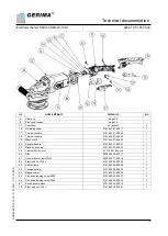
Page 18: ...3 0101 442 21 00004 1 20 Adapter handle 0101 442 21 00001 1 22 Machine housing 0101 552 20 00002 1 30 Cable with crommet 0101 482 19 0xxxx 1 44 Disc 0000 022 14 00131 1 47 Countersunk screw M3x10 0000 022 17 00218 1 56 Electronic unit 230 V 0101 482 20 00009 1 58 Cable clamp 0101 482 20 00008 1 59 Tension spring 0101 482 20 00020 1 60 Magnetic disc 0101 552 21 00005 1 65 Pan head tapping screw 698...

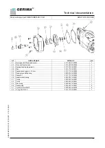
Page 19: ...e ball bearing 0101 173 15 00005 1 11 Fixed bearing coverr 0101 173 15 00006 1 13A Armature complete 230 V 0101 552 21 00004 1 13B Armature complete 120 V on request 1 15 Deep groove ball bearing 0101 452 20 00021 1 16 Rubber bushing 0101 552 21 00006 1 17 Air baffle 0101 552 21 00007 1 18 Pan head tapping screw 0101 552 21 00008 2 19A Stator 230 V 0101 552 21 00009 1 19B Stator 120 V on request 1...

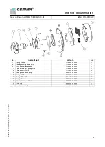
Page 20: ...0101 482 20 00002 1 5 Round handle with puncture protection Ø58 145 0101 482 19 00025 1 6 Guide plate holder 0101 482 20 00001 1 10 Holding plate handle 0101 442 18 00021 1 15 Guide plate Ø150 0101 442 21 00012 1 32 Locking bolt with locking groove 0000 032 16 00124 1 33 Thread insert M8x15 0000 022 14 00117 2 37 Allen screw M5x20 0000 022 15 00221 4 38 Allen screw M8x20 0000 022 14 00205 2 46 Cou...

Page 21: ...aring housing upper part 0101 472 19 00001 1 25 Disc 0101 172 14 00011 1 26 Spacer bevel gear t 1 5 mm 0101 172 14 00005 1 35 Deep groove ball bearing 0000 012 14 00033 1 39 Spacer 0 1 0101 173 15 00002 1 40 Needle roller bearing 0000 032 14 00007 1 51 Circlip 0000 022 14 00001 1 52 Circlip 0000 022 16 00251 1 54 Disc spring 0000 022 15 00022 1 55 Sealing plug 0000 032 16 00051 2 61 Cylinder screw...

Page 22: ... 00004 1 9 Drive shaft divided below 0101 442 19 00003 1 11 Flywheel with spring magazine 0101 442 19 00002 1 29 Thread insert M6x14 0101 143 09 00023 3 34 Deep groove ball bearing 0000 012 14 00035 1 41 O ring 20 3x2 4 0000 042 14 00013 1 42 O ring 59 99x2 62 0000 042 14 00011 1 43 O ring 12x1 0000 042 19 00001 1 48 Countersunk screw M5x16 0000 022 14 00116 4 53 Snap ring 0000 022 14 00202 1 63 C...

Page 23: ...the machine was used for its intended purpose The guarantee does not cover in particular operational wear and tear improper use partially or wholly disassembled machines damage arising from overloading the machine or from the incorrect use of the milling tool the use of non genuine unauthorized or defective parts damage caused by the machine to the workpiece use of excessive force consequential da...

Page 24: ...ovisions of the Machinery Directive 2006 42 EC The above product fulfills the relevant requirements of the following guidelines Directive 2006 42 EC of the European Parliament and the Council of 17 May 2006 on machinery and amending Directive 95 16 EC recast 2006 42 EC Directive 2014 35 EU of the European Parliament and of the Council of 26 February 2014 on the harmonisation of the laws of the Mem...

Reviews: