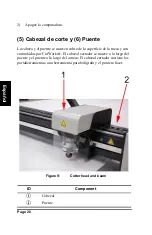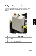
Page 17
Es
pa
ñol
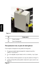
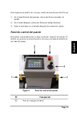
(4a) Caja de control
La caja de control es un componente separado que controla, junto con el
ordenador, el corte. Normalmente se posiciona en el escritorio de control.
Figure 7:
Caja de control
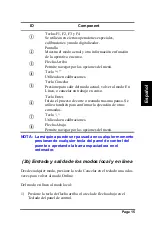
ID
Component
Regulador de presión
Se utiliza para regular la presión del portador de
herramienta 3 del bolígrafo y de subida de las
herramientas.
Reguladores de presión
Se utilizan para regular las presiones de los portadores
de herramientas 1 y 2 respectivamente
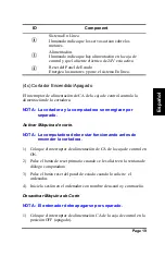
Panel de estado
Vea Figura 8
Luz indicadora de sistema energizado.
Se ilumina cuando los motores tienen alimentación.
Paro de emergencia.
Pulsar cuando pueda haber peligro para las personas, la
máquina o el material a cortar.
Summary of Contents for DCS 1500
Page 1: ...Started Getting Manual Manual de Inicio...
Page 2: ......
Page 3: ...DCS 1500 DCS 2500 GERBERcutter Getting Started Manual...
Page 4: ......
Page 61: ...DCS 1500 DCS 2500 GERBERcutter Manual de inicio...
Page 62: ......
Page 64: ...Page iv Espa ol...
Page 113: ...DCS 1500 DCS 2500 GERBERcutter...
Page 114: ......
Page 116: ...Page iv...
Page 117: ...Page v III III 1 1 1 2 2 2 2 2 3 3 3 5 5 5 6 6 6 6 6 6 6 7 7 7...
Page 119: ...Page vii 32 32 32 33 33 34 DCS 1500 2500 34 45 49 DCS 2500 49 50 50 50 V 51 51 52 53...
Page 120: ......
Page 121: ...Page 1 DCS1500 2500 GERBERcutter DCS 1500 2500 GERBERcutter Windows 3 1...
Page 123: ...Page 3 84 8 984 7080 GERBERcutter GERBERcutter...
Page 124: ...Page 4...
Page 125: ...Page 5 2...
Page 126: ...Page 6 A C...
Page 127: ...Page 7 Class IIIr 5 mW 670 nm CutWorks WEEE 2005 8 13 2002 96 EC...
Page 128: ...Page 8 1 WEEE...
Page 130: ...Page 10 1 BCP GERBER...
Page 131: ...Page 11 DCS 2500 1 E Stop 2 2 2 3 2 4...
Page 132: ...Page 12 2 3...
Page 133: ...Page 13 2a 1 3 2 3 3 6 4 6 1 2 3 3 BCP BCP...
Page 134: ...Page 14 4 5...
Page 135: ...Page 15 3a 5 F1 F2 F3 F4...
Page 136: ...Page 16 3b 1 2 1...
Page 137: ...Page 17 1 2 a 3c 1 2 3 4 5 4 Gerber 4a...
Page 138: ...Page 18 6 3 1 2 7 AC...
Page 139: ...Page 19 4b 7 X Y T 24V...
Page 140: ...Page 20 4c AC 1 AC 2 3 4 1 AC 2...
Page 141: ...Page 21 5 6 CutWorks 8...
Page 142: ...Page 22 7 9 8 9...
Page 143: ...Page 23 10 DCS 2500 3 O C O 10 10 C 11...
Page 144: ...Page 24 11...
Page 145: ...Page 25 11 3 12 1 2 3...
Page 146: ...Page 26 DCS 1500 2500 DCS 1500 2500 V V V V U...
Page 147: ...Page 27 3 DCS 1500 2500 13...
Page 148: ...Page 28 5 64 1 14 1 Cutting tool installation 2 3 5 64 5 64...
Page 149: ...Page 29 1 2 0 Depth gauge with flat surface 3 4 5 16 6...
Page 150: ...Page 30 16 7 17 8 4...
Page 151: ...Page 31 17 9 4 0 010 0 015 10 11...
Page 153: ...Page 33 CAD DCS 1500 2500 1 10 1 32 1 2 AccuMark CutWorks GERBERcutter...
Page 156: ...Page 36 18 NC 8 GT TEMPLATE nc M19 19 9 19 a Accumark Lectra b 0 250 c...
Page 157: ...Page 37 19 NC M19 20 11 14 V...
Page 158: ...Page 38 20 10 21...
Page 159: ...Page 39 21 11 12 Notcher 22 13 Cut 22 14 22 False 0 00 0 00 N Hits 1...
Page 160: ...Page 40 22 15 Cut Cut cut 16 Cut 22 17 23 30 00 25 30 00 1 00...
Page 161: ...Page 41 Map Layers to Tools Cut layer 18 19 18 in 45 72 cm 1 24...
Page 162: ...Page 42 24 18 1 20 21...
Page 163: ...Page 43 25 22 23 26 a b c...
Page 164: ...Page 44 26 24 1 in 2 54 cm 1 in 2 54 cm 25 26 DCS 1500 2500 GERBERcutter...
Page 165: ...Page 45 C X Y C X Y BCP C GERBERcutter E Stop...
Page 166: ...Page 46 X Y CutWorks 0 0...
Page 167: ...Page 47 AccuMark V X0 Y0 X Y C...
Page 168: ...Page 48 X Y...
Page 169: ...Page 49 DCS 2500 1 800 321 2448 800 820 1661 InfoJet Inkjet InfoMark 1 75 Theta theta 4...
Page 171: ...Page 51 V 45 3 16 TL 354 45 1 4 TL 257 45 5 16 TL 267 60 3 16 TL 256 7 V 90 0 040 TL 056 8...
Page 174: ...Page 54...
Page 175: ......

