background image

40


中文

Y

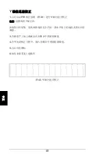
轴往返差校正


1.

点击启动

F/R

校正按击(图

39

)进行

Y

轴往返差校正


注意

绘图机将开始打印。


2.

检查打印结果,查找两条线段完全在同一条水平线上的线段及其对应的

数值。


3.

在数值

7

上加上或减去从步骤

2

中得到的数值


4.

Y

间距校正方框中,输入步骤

3

中得到的新数值。


5.

点击应用图标


6.

如有必要重复上述操作


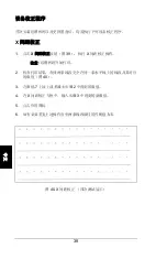
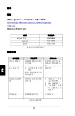
43. Y

轴往返差校正


Summary of Contents for GERBERplotter XLp Series

Page 1: ......

Page 2: ......

Page 3: ......

Page 4: ...shall not constitute any right or license to do so The information in this document is subject to change without notice Gerber Technology its subsidiaries and affiliates shall not be liable for error...

Page 5: ...pport 1 Safety Instructions 3 Hardware Installation 7 Software Overview 21 WinPlot Installation 21 XLp Interface Software Installation 22 Calibration Procedures 38 Complete a Test Plot on the GERBERpl...

Page 6: ...18 Plotter with paper installed 19 Figure 19 Installed Inkjet Cartridges XLp95 20 Figure 20 WinPlot Installation screen 21 Figure 21 XLp Interface Installation screen 22 Figure 22 Gerber Device Config...

Page 7: ......

Page 8: ...r Support Contact the Regional Customer Solution Center with support or technical questions Write the specified information on the blanks below to have it available when calling Regional Customer Solu...

Page 9: ...h China Phone 86 21 5445 0505 Europe Phone 32 2 716 0311 Vietnam Phone 84 8 984 7080 Waste Electrical and Electronic Equipment WEEE Attention European Union Member States All Gerber equipment is label...

Page 10: ...autions Warnings and cautions precede some steps or procedures Always follow these precautions to prevent personal injury or equipment damage Warnings are put before procedures that could result in pe...

Page 11: ...injury Make sure no one else is near the plotter during operation Replacing Parts Notify a Gerber Field Service Representative of any broken or missing parts Do not use parts or modifications that ar...

Page 12: ...UP position loosely grips the paper and is used when loading paper 2 Front Cover This covers the paper and inkjet cartridges 3 Control Panel The Control Panel controls plotter functions see Figure 3...

Page 13: ...Panel description 1 Arrow Keys Used to navigate commands on the LCD screen in four directions left right up and down 2 LCD Screen Displays and controls the plotter LCD screen commands 3 Menu button Us...

Page 14: ...o complete the Hardware Installation 1 Lift and remove the top of the crate to view the XLp plotter Figure 4 and contents Figure 5 Figure 4 XLp Plotter in crate Figure 5 Crate contents Key to Figure 1...

Page 15: ...____________________ 8 English 2 Remove the cardboard Component Box and review contents Figure 6 Figure 6 Component Box Key to Figure 1 Adhesive tape 2 USB Cable 3 Hex Wrenches 4 HP Inkjet Cartridge s...

Page 16: ...re 7 Figure 7 Right Side Column removed and balanced 4 Hold Crossbeam up to Right Side Column Figure 8 and align with the Screws 5 Use the Hex Wrenches and Screws to attach the crossbeam to the Right...

Page 17: ...crews to attach Figure 9 Repeat on the opposite side Figure 9 Two screws attaching Head Unit and Crossbeam Key to Figure 1 Screws 8 On the interior of the Right Side Column remove the Feed Motor Cable...

Page 18: ...end of the USB cable into the port underneath the Right Side Column Figure 11 10 Plug the opposite end of the USB cable into the computer NOTE If a network cable is used plug it into the port next to...

Page 19: ...es lose its alignment If it is not lying flat twist the Rubber Stops located underneath the left and right of the Front Cover until it rests evenly on both sides Figure 12 12 Remove the Screw next to...

Page 20: ...________________________________________________ 13 English 13 Use the Voltage Switch to select 110V or 220V Figure 13 Voltage switch...

Page 21: ..._________________________________________ 14 English 13 Locate the Power Cord pocket on the side of the crate Figure 14 Remove the panel and retrieve the Power Cord stored inside Figure 14 Power Cord...

Page 22: ...e Power Cord Socket Figure 15 15 Plug the opposite end into a wall electrical socket 16 Push the Power Switch to the I ON position to turn the plotter power on NOTE The plotter will beep when powered...

Page 23: ...Figure 16 Figure 16 Paper roll and components Key to Figure 1 Paper Roll 2 Feed Roll Bar 3 Mandrels 18 Place Mandrels on each end of the Feed Roll Bar and use the attached black levers to tighten nex...

Page 24: ...UP position This disengages the drive to move the paper and allows a new roll to be installed 21 Place the paper above the Crossbeam under the Front Dancer Bar and feed it to the back of the plotter...

Page 25: ...and Nip Bar Figure 19 Feeding paper toward front of plotter 25 Place paper under the Front Dancer Bar and pull forward a To let paper fall to the floor Place the paper over the Front Dancer Bar b To w...

Page 26: ...e packages from the Component Box Figure 6 Remove and discard the green film attached to the bottom of the cartridge 28 Lift the Front Cover to reveal the Inkjet Cartridge Holder and lift the top of t...

Page 27: ...________________________________________________ 20 English Figure 22 Installed Inkjet Cartridges XLp95...

Page 28: ...er they will need to upgrade AccuMark or supply a separate networked Windows PC to run WinPlot with the XLp plotter update See the documentation on each software CD to view additional System Requireme...

Page 29: ...click XLp Update for Version 8 2 2 8 4 0 Install WinPlot AccuMark first 7 Follow the InstallShield prompts to install the XLp Update XLp Interface Software Installation 1 Insert the XLp Interface sof...

Page 30: ...n 1 On the Start menu point to Control Panel 2 Double click the Gerber Device icon 3 The Gerber Device Configuration window will appear Figure 25 4 Click the Plotter tab 5 In the Type box select XLP U...

Page 31: ...each screen TCP IP Configuration NOTE The plotter must be powered on and plugged in to the computer before beginning the TCP IP connection 1 Right click the XLp Interface icon located on the Status Ar...

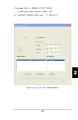
Page 32: ...________________________________________________ 25 English 4 Select IP Communication Figure 27 System Setting initial screen...

Page 33: ...______________________________________ 26 English 5 In the Network Adapter List select the desired network connection for the plotter 6 Click the Lan Scan button Figure 28 System Setting window IP Com...

Page 34: ...MAC Address List box will propagate after the Lan Scan is complete 7 Select the desired Mac Address in the Mac Address List box 8 Type the IP Address Subnet Mask and Gateway specific to the network be...

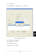
Page 35: ...______________________________________ 28 English 9 Click the Connect button 10 The Setting Succeed window will appear Click OK to confirm the configurations Figure 30 System Setting window Setting Su...

Page 36: ...ogram and Plotter window will appear Click OK to confirm Figure 31 Plotter and program restart window 13 Click the Close button to close the XLp Interface The plotter will beep and the LCD Screen will...

Page 37: ...________________________________________________ 30 English 16 The window in Figure 32 will appear with tabs for further configuration Figure 32 System Setting window after configuration...

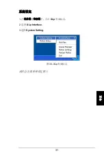
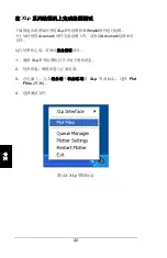
Page 38: ..._________________ 31 English System Setting 1 Click the XLp Interface Icon located on the Status Area of the Task Bar 2 Select XLp Interface 3 Select System Setting Figure 33 XLp Interface Icon The Sy...

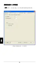
Page 39: ...______________________________________ 32 English System Setting Window Plot tab The Plot tab allows configuration of the Line Width Y Plot Origin and ink usage settings Figure 34 System Setting windo...

Page 40: ...________________________________________________ 33 English System Setting Window Ink tab The Ink tab allows configuration of the Ink Counter Reset Values Figure 35 System Setting window Ink tab...

Page 41: ..._________________________________ 34 English System Setting Window Paper tab The Paper tab allows configuration of the Paper Roll length and corresponding paper preferences Figure 36 System Setting wi...

Page 42: ...English System Setting Window System tab The System tab allows selection of the units of measure and settings such as the Top Cover Alarm to run a Cartridge Auto test and to Clean the Cartridge After...

Page 43: ...________________________________________ 36 English System Setting Window Communication tab The Communication tab allows selection of USB or IP Communication Figure 38 System Setting window Communicat...

Page 44: ...g Window Calibration tab The Calibration settings allow configuration of the following calibrations Cartridge Alignment Cartridge Overlap Y Head Calibration Y Gap Calibration and X Length and Y Length...

Page 45: ...X Gap calibration NOTE The plotter will begin printing 2 Check the plot for the line and corresponding numeric value that represents the best match of the two printed lines Figure 40 3 Add or subtract...

Page 46: ...ibration if required Figure 41 Cartridge Overlap calibration Cartridge Separation Alignment Calibration NOTE The default value is 261 2 61 cm or 261 mm 1 Click the Start Cartridge Separation Alignment...

Page 47: ...ignment Calibration NOTE The plotter will begin printing 2 Check the plot for the line and corresponding numeric value that represents the best match of the two printed lines 3 Add or subtract the val...

Page 48: ...OTE The test must be run with the paper falling to the floor 1 Click the Start Box Test button Figure 39 to run the Box Test NOTE The plotter will begin printing 2 When the printing is complete cut th...

Page 49: ...and WinPlot To complete a plot using AccuMark refer to the AccuMark plotting documentation Read the Safety Instructions section before operating the plotter 1 Ensure the XLp Series plotter is turned o...

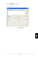
Page 50: ...________________________________________________ 43 English The WinPlot window will appear Figure 45 5 Click Add Figure 45 WinPlot screen...

Page 51: ...ose files to plot window will appear Figure 46 6 Browse to one of the following locations c Program Files Gerber Technology AccuMark V8 WinPlot Samples or c WinPlot Samples 7 Select 1MeterMarker PLT a...

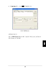
Page 52: ...__ 45 English 8 In the WinPlot box click Plot to begin plotting Figure 47 WinPlot box The plotter will begin printing Congratulations A plot using the GERBERplotter XLp Series has been completed The p...

Page 53: ...hooting Error message Possible cause Solution Exceed plot width Marker parameters exceed plotter width and length Check if the width of the plot file exceeds the range of plotter setting Invalid X ink...

Page 54: ...ll Inner Diameter 7 6cm 2 9 in Paper Roll Outer Diameter 30cm 18 8 in Plot Paper Thickness 40 100g 1 4 oz 3 5 oz Max Plot Width 183cm 72 File Format HPGL DXF NC PC Interface USB and Network Parameter...

Page 55: ...he plotter The Mandrels on the Feed Roller are adjustable to accommodate different paper widths Front Cover The Front Cover must be in the down position for the plotter to function When lifted it prov...

Page 56: ...he Nip Bar The Pinch Rollers hold the paper in place and feed it through the plotter The Nip Bar tension is adjusted using the Nip Bar Lever ON OFF Switch The main power switch that is located behind...

Page 57: ......

Page 58: ......

Page 59: ...encia o derecho alguno para realizar tales actividades La informaci n de este documento est sujeta a cambios sin previo aviso Gerber Technology sus empresas subsidiarias y afiliadas no ser n responsab...

Page 60: ...d 3 Instalaci n del hardware 7 Descripci n del software 21 Instalaci n de WinPlot 22 Instalaci n del software de la interfaz del XLp 23 Procedimientos de calibraci n 39 Haga un gr fico de prueba en el...

Page 61: ...el graficador 18 Figura 21 Graficador con papel instalado 19 Figura 22 Cartuchos de chorro de tinta instalados XLp95 20 Figura 23 Pantalla de instalaci n de WinPlot 22 Figura 24 Ventana de instalaci n...

Page 62: ...igura 44 Icono de la interfaz del XLp 44 Figura 45 Pantalla de WinPlot 45 Figura 46 Ventana Choose files to plot Elegir archivos a graficar 46 Figura 47 Cuadro WinPlot 46 Tabla 1 Etiquetas de segurida...

Page 63: ...a o desea efectuar una consulta t cnica comun quese con el Centro regional de atenci n al cliente Escriba la informaci n especificada en los siguientes espacios en blanco para que la tenga disponible...

Page 64: ...a ol China Tel fono 86 21 5445 0505 Europa Tel fono 32 2 716 0311 Vietnam Tel fono 84 8 984 7080 Directiva europea de residuos de aparatos el ctricos y electr nicos WEEE Atenci n Estados miembros de l...

Page 65: ...bla 1 Etiquetas de seguridad Advertencias y precauciones Algunos pasos o procedimientos est n acompa ados de advertencias y precauciones Siempre observe estas precauciones para prevenir lesiones perso...

Page 66: ...les mantenga las manos alejadas de las piezas m viles del graficador Compruebe que no haya nadie cerca del graficador durante su operaci n Cambios de piezas Notifique a un representante del Servicio l...

Page 67: ...PERIOR sujeta flojamente el papel y se utiliza durante la carga del papel 2 Cubierta delantera Cubre el papel y los cartuchos de chorro de tinta 3 Panel de control El panel de control controla las fun...

Page 68: ...as de flechas Se usan para navegar los mandos de la pantalla LCD en cuatro direcciones izquierda derecha arriba y abajo 2 Pantalla LCD Presenta y controla los mandos de la pantalla LCD del graficador...

Page 69: ...ci n del hardware 1 Levante y quite la parte superior de la caja para ver el graficador XLp Figura 4 y su contenido Figura 5 Figura 4 Graficador XLp en la caja Figura 5 Contenidos de la caja Claves de...

Page 70: ...Espa ol 2 Saque la caja de componentes de cart n y examine el contenido Figura 6 Figura 6 Caja de componentes Claves de la figura 1 Cinta adhesiva 2 Cable USB 3 Llaves hexagonales 4 Cartucho s de cho...

Page 71: ...las Figura 7 Figura 7 Columna lateral derecha fuera de la caja y equilibrada 4 Sostenga el travesa o contra la columna lateral derecha Figura 8 y alin elo con los tornillos 5 Con los tornillos suminis...

Page 72: ...na lateral derecha 7 Coloque la unidad superior encima de las dos columnas laterales Atornille los tornillos de la izquierda y de la derecha Figura 9 Repita este procedimiento en el lado opuesto Figur...

Page 73: ...de la columna lateral derecha Figura 10 Figura 10 Cable del motor de alimentaci n dentro de la columna lateral derecha 9 Enchufe el extremo B del cable USB en el puerto que est debajo de la columna l...

Page 74: ...va durante el env o y pierda su alineaci n Si no est colocada en posici n horizontal gire los topes de goma situados debajo de la izquierda y la derecha de la cubierta delantera hasta que quede apoyad...

Page 75: ..._____________________________ 13 Espa ol Figura 12 Tope de goma izquierdo y tornillo Claves de la figura 1 Tope de goma 2 Tornillo 13 Con el conmutador de tensi n seleccione 110 V o 220 V Figura 13 Co...

Page 76: ...ble de alimentaci n que est adentro Figura 14 Toma del cable de alimentaci n 14 Enchufe el cable de alimentaci n en la toma del cable de alimentaci n Figura 15 15 Enchufe el extremo opuesto en el toma...

Page 77: ...ma 17 Inserte la barra del rodillo de alimentaci n a trav s del n cleo hueco del rodillo de papel Figura 16 Figura 16 Rodillo de papel y componentes Claves de la figura 1 Rodillo de papel 2 Barra del...

Page 78: ...recci n de las flechas amarillas y coloque la palanca de la barra de presi n en la posici n SUPERIOR De esa forma se desengancha el accionador para mover el papel y se permite instalar un rodillo nuev...

Page 79: ...igura 18 Papel alimentado a trav s de la barra de presi n y los rodillos de arrastre 24 Tire del papel hacia el frente del graficador y a trav s de los rodillos de arrastre y de la barra de presi n Fi...

Page 80: ...apel caiga en el piso Deje el papel debajo de la barra m vil frontal b Para enrollar el papel en el rodillo Con la cinta adhesiva suministrada pegue el extremo del papel a la barra tensora del papel F...

Page 81: ...e inferior del cartucho 28 Levante la cubierta delantera para dejar al descubierto el portacartuchos de chorro de tinta y levante la parte superior de la primera ranura 29 Coloque el cartucho de chorr...

Page 82: ...________________________________________________ 20 Espa ol Figura 22 Cartuchos de chorro de tinta instalados XLp95...

Page 83: ...a de AccuMark anterior a la 8 2 2 y utiliza un graficador XLp tendr que actualizar AccuMark o suministrar una PC aparte con Windows y conectada red para poder ejecutar WinPlot con la actualizaci n del...

Page 84: ...e GT haga clic en Install WinPlot Software Instalar software WinPlot 4 Siga las indicaciones del InstallShield para instalar WinPlot 5 Vuelva a la pantalla de instalaci n de WinPlot una vez que est in...

Page 85: ...l XLp en la unidad de CD 2 Aparecer la ventana de instalaci n de la interfaz del XLp Figura 24 Figura 24 Ventana de instalaci n de la interfaz del XLp 3 Abajo de GT Programs haga clic en Install XLp S...

Page 86: ...doble clic en el icono del dispositivo Gerber 3 Aparecer la ventana Gerber Device Configuration Configuraci n del dispositivo Gerber Figura 25 4 Haga clic en la pesta a Plotter Graficador 5 En el cuad...

Page 87: ...ido y enchufado a la computadora antes de comenzar la conexi n TCP IP 1 Haga clic con el bot n derecho del rat n en el icono de Interfaz del XLp situado en el rea de estatus de la barra de tareas 2 Se...

Page 88: ...____________________ 26 Espa ol Figura 27 Pantalla inicial System Setting 5 En Network Adapter List Lista de adaptador de red seleccione la conexi n de red deseada para el graficador 6 Haga clic en el...

Page 89: ...se haga el Lan Scan se propagar el cuadro de Lista de direcciones de MAC 7 En el cuadro Mac Address List Lista de direcciones de Mac seleccione la direcci n Mac deseada 8 Introduzca IP Address Direcc...

Page 90: ...____ 28 Espa ol Figura 29 Ventana System Setting comunicaci n IP 9 Haga clic en el bot n Connect Conectar 10 Aparecer la ventana Setting Succeed Se establecieron los ajustes satisfactoriamente Haga cl...

Page 91: ...Espa ol Figura 30 Ventana System Setting cuadro Setting Succeed 11 Haga clic en Set IP Address Fijar direcci n de IP 12 Aparecer la ventana Please Restart Program and Plotter Favor reiniciar el progr...

Page 92: ...Haga clic en el bot n Close Cerrar para cerrar la XLp Interface El graficador emitir un pitido y la pantalla LCD indicar el reinicio 14 Apague el graficador XLp y luego vuelva a encenderlo 15 Repita...

Page 93: ...________________________________________________ 31 Espa ol Figura 32 Ventana System Setting despu s de la configuraci n...

Page 94: ...Espa ol Ajustes del sistema 1 Haga clic en el icono de Interfaz del XLp situado en el rea de estatus de la barra de tareas 2 Seleccione XLp Interface 3 Seleccione System Setting Figura 33 Icono de la...

Page 95: ...________ 33 Espa ol Ventana System Setting pesta a Plot La pesta a Plot Gr fico permite configurar los par metros Line Width ancho de l nea Y Plot Origin origen del gr fico Y y de uso de la tinta Figu...

Page 96: ...___________________________________ 34 Espa ol Ventana System Setting pesta a Ink La pesta a Ink Tinta permite configurar los valores de reajuste del contador de tinta Figura 35 Ventana System Setting...

Page 97: ...________________ 35 Espa ol Ventana System Setting pesta a Paper La pesta a Paper Papel permite configurar la longitud del rodillo de papel y las preferencias de papel correspondientes Figura 36 Venta...

Page 98: ...ystem Sistema permite seleccionar las unidades de medici n y par metros como Top Cover Alarm Alarma de cubierta superior ejecutar Cartridge Auto test Prueba autom tica del cartucho y Clean the Cartrid...

Page 99: ..._______________________ 37 Espa ol Ventana System Setting pesta a Communication La pesta a Communication Comunicaci n permite seleccionar el tipo de comunicaci n USB o IP Figura 38 Ventana System Sett...

Page 100: ...n configurar las siguientes calibraciones Cartridge Alignment Alineaci n del cartucho Cartridge Overlap Traslapo del cartucho Y Head Calibration Calibraci n del cabezal Y Y Gap Calibration Calibraci n...

Page 101: ...cutar dicha calibraci n NOTA El graficador comenzar a imprimir 2 Examine el gr fico para observar la l nea y determinar el correspondiente valor num rico que mejor represente las dos l neas impresas F...

Page 102: ...39 para ejecutar la calibraci n correspondiente NOTA El graficador comenzar a imprimir 2 Examine el gr fico para observar la l nea y determinar el correspondiente valor num rico que mejor represente...

Page 103: ...jecutar la alineaci n del cabezal Y NOTA El graficador comenzar a imprimir 2 Examine el gr fico para observar la l nea y determinar el correspondiente valor num rico que mejor represente las dos l nea...

Page 104: ...o Y Gap 5 Haga clic en Apply 6 Repita la calibraci n de ser necesario Figura 43 Calibraci n de la alineaci n de avance inversi n Longitud X y longitud Y Prueba de cuadro La prueba del cuadro Box Test...

Page 105: ...direcciones X e Y Introduzca estos valores en el cuadro Actual Length Longitud real 4 Haga clic en Confirm Confirmar 5 Haga clic en Apply 6 Actualice los nuevos valores del paso 3 en los cuadros XLen...

Page 106: ...graficado con AccuMark Lea el apartado Instrucciones de seguridad antes de poner en funcionamiento el graficador 1 Compruebe que el graficador serie XLp est encendido y en l nea 2 Compruebe que el pa...

Page 107: ...Aparecer la ventana Choose files to plot Elegir archivos a graficar Figura 46 6 Explore en una de las siguientes localidades c Program Files Gerber Technology AccuMark V8 WinPlot Samples o c WinPlot S...

Page 108: ...to plot Elegir archivos a graficar 8 En el cuadro WinPlot haga clic en Plot para comenzar a graficar Figura 47 Cuadro WinPlot El graficador comenzar a imprimir Felicitaciones Se Imprimi un gr fico con...

Page 109: ...os del marcador exceden la anchura y longitud del graficador Averig e si la anchura del archivo del gr fico sobrepasa los l mites del ajuste del graficador Invalid X ink jet cartridge Cartucho de chor...

Page 110: ...pel 7 6 cm 2 9 pulg Di metro externo del rollo de papel 30 cm 18 8 pulg Grosor del papel de graficaci n 40 100 g 1 4 a 3 5 onzas Anchura m xima de gr fico 183 cm 72 pulg Formato de archivo HPGL DXF NC...

Page 111: ...nsecuente a trav s del graficador Barra m vil frontal Esta barra se sit a detr s de la barra tensora del papel y ayuda a la alimentaci n del papel despu s de la impresi n Barra tensora del papel El pa...

Page 112: ...l papel y se utiliza durante la carga del papel Panel de control Las funciones del graficador se controlan a trav s del panel de control Portacartuchos de chorro de tinta Esta pieza sostiene los cartu...

Page 113: ......

Page 114: ......

Page 115: ...i 2010 GERBERplotter XLp XLp WinPlot GERBERplotter 94134002 10 10 D Gerber Technology 24 Industrial Park Road West Tolland CT 06084 USA Telephone 860 871 8082 99 16 1 2 200233 86 21 5445 0505...

Page 116: ...ii 1 3 7 21 WINPLOT 21 XLP 22 38 XLP 42 46 46 47 48...

Page 117: ...0 11 11 USB 12 12 13 13 14 14 15 15 16 16 17 17 17 18 18 19 19 20 20 21 20 22 XLp95 21 23 WinPlot 23 24 XLp 24 25 25 26 XLp 26 27 27 28 IP Communication 28 29 IP Communication 29 30 30 31 31 32 32 33...

Page 118: ...iv 41 X 41 42 1 2 Y 42 43 Y 42 44 XLp 44 45 WinPlot 45 46 46 47 WinPlot 47 1 3 2 46 3 46 4 47...

Page 119: ...___________________________ ____________________________ ____________________________ GERBERplotter XLp Series _ ___________________________ ___________________________ www gerbertechnology com defaul...

Page 120: ...2 1 800 826 3243 1 860 871 8082 1 866 796 8570 86 21 5445 0505 32 2 716 0311 84 8 984 7080 WEEE 2005 8 13 WEEE 1 WEEE...

Page 121: ...3 XLp 1 Symbol Description 1...

Page 122: ...4...

Page 123: ...5 2 XLP 1 2 3 3 4 5 XLp...

Page 124: ...6 3 1 LCD 2 LCD LCD 3 LCD 4 LCD...

Page 125: ...7 2 1 XLp 4 5 4 XLp 5 1 2 3 4 4 72 1 82 5...

Page 126: ...8 2 6 6 1 2 USB 3 4 HP 5 6 7...

Page 127: ...9 3 7 7 4 8 5 6 4 5 8...

Page 128: ...10 7 9 9 1 8 10 10...

Page 129: ...11 9 USB B 11 10 USB USB 11 USB...

Page 130: ...12 11 12 12 12 12 1 2...

Page 131: ...13 13 110V 220V 13...

Page 132: ...14 14 14...

Page 133: ...15 14 15 15 16 I 15 1 2...

Page 134: ...16 17 16 16 1 2 3 18 17 17 1 2 3...

Page 135: ...17 19 20 21 22 23 18 18...

Page 136: ...18 24 19 25 a b 20...

Page 137: ...19 26 21 27 6 HP45 28 29 HP45 30...

Page 138: ...20 22 XLp95...

Page 139: ...21 XLp WinPlot AccuMark XLp Interface XLp AccuMark WinPlot 8 2 2 Accumark 8 2 2 Windows PC WinPlot XLp Accumark Winplot XLp Accumark 6 Winplot 1 CD 2 WinPlot Installation 23 23 WinPlot...

Page 140: ...re 4 InstallShield WinPlot 5 WinPlot WinPlot Installation 6 GT Programs XLp Update for Version 8 2 2 or AccuMark 8 4 0 Install WinPlot AccuMark first 7 InstallShield XLp 1 XLp CD 2 XLp 24 24 XLp 3 GT...

Page 141: ...23 Gerber 1 2 3 Gerber 25 4 Plotter 5 XLP USB PLOTTER XLP PLOTTER 6 7 ok 25...

Page 142: ...24 TCP IP TCP IP 1 XLp 2 XLp Interface 3 System Setting 26 XLp 27...

Page 143: ...25 4 IP Communication 27...

Page 144: ...26 5 6 lan scan 28 IP Communication...

Page 145: ...27 lan scan MAC 7 MAC MAC 8 IP 29 IP Communication...

Page 146: ...28 9 Connect 10 ok 30...

Page 147: ...29 11 IP 12 OK 31 13 XLp 14 15 1 3 XLp...

Page 148: ...30 16 32 32...

Page 149: ...31 1 XLp 2 XLp Interface 3 System Setting 33 XLp...

Page 150: ...32 Y 34...

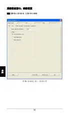
Page 151: ...33 35...

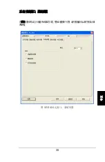
Page 152: ...34 36...

Page 153: ...35 37...

Page 154: ...36 USB IP 38...

Page 155: ...37 X Y Y X Y Box 39 XLP95...

Page 156: ...38 X 1 X 39 X 2 40 3 7 2 4 X 3 5 6 40 X...

Page 157: ...39 X 1 X 39 2 3 X 2 4 5 41 X 1 2 Y 261 2 61 cm 261 mm 1 1 2 Y 39 Y 2 3 261 2 4 1 2 3 5 6 42 1 2 Y...

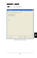
Page 158: ...40 Y 1 F R 39 Y 2 3 7 2 4 Y 3 5 6 43 Y...

Page 159: ...41 X Y Box Box 1m x 1 m 1mm 1mm Box 1 Box 39 Box 2 3 X Y 4 5 6 3 X Y 7 8 9...

Page 160: ...42 XLp XLp Winplot Accumark Accumark 1 XLp 2 3 XLp Plot Files 36 4 44 XLp...

Page 161: ...43 WinPlot 45 5 45 WinPlot...

Page 162: ...44 46 6 c Program Files Gerber Technology AccuMark V8 WinPlot Samples or c WinPlot Samples 7 1MeterMarker PLT Add file s 46 46...

Page 163: ...45 8 WinPlot 47 WinPlot GERBERplotter XLp plt...

Page 164: ...46 800 321 2448 https www gerberscientific net GT eCommerce login aspx HP 45 558500006 94714000 94541000 2 X 1 2 1 2 3 1 2 3...

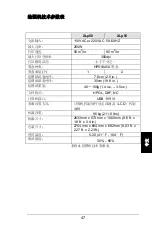
Page 165: ...2 hr 95 m 2 hr 300dpi HP51645A 1 2 7 6cm 2 9 in 30cm 18 8 in 40 100g 1 4 oz 3 5 oz HPGL DXF NC USB LCD 96 kg 211 6 lbs 2633mm x 573 mm x 1060 mm 8 6 ft x 1 8 ft x 3 4 in 2754 mm x 694 mm x 682 mm 9 0...

Page 166: ...48...

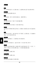
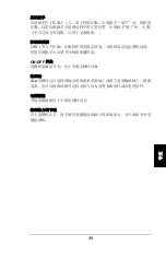
Page 167: ...49 ON OFF XLp...

Page 168: ......

Page 169: ......

Page 170: ......

Reviews: