


OSD Menu Options and Functions
LED Brightness Settings
Function
Manually adjust the camera lens.
Press
SET
to adjust the lens brightness.
Includes these options: 1/60, 1/100, 1/250,
1/500, 1/2000, 1/5000, 1/10000, 1/100000.
Press
SET
to manually adjust the shutter
speed.
Not available when the LENS is set at DC.
Turn off BLC function.
Press
SET
to configure the areas.
Press
SET
to adjust the sensitivity values.
Turn off AGC function.
Press
SET
to adjust the AGC ratio values.
Auto Tracking White Balance
Automatic White Balance
Press
SET
to select the mode from 1 to 4.
Press
SET
to adjust Red and Blue gain.
Adjust the Contrast from values 0 to 255.
Adjust the Sharpness from values 0 to 255.
Adjust CB_GAIN from values 0 to 255.
Adjust CR_GAIN from values 0 to 255.
Press
SET
to name the camera.
Select
ON
to reverse the image.
Select
ON
and press
SET
to configure
MOTION areas.
Select
ON
and press
SET
to configure
PRIVACY areas.
Adjust the gamma values to control brightness.
Higher gamma value shows darker images.
Press
SET
to change the language setting of
OSD menu options.
Press
SET
to restore to the factory defaults.
Close the OSD menu.
Main Menu
LENS
SHUTTER
BLC
(Backlight
Compensation)
AGC
(Automatic
Gain Control)
WHITE BAL.
(White Balance)
ADJUST
FUNCTION
RESET
EXIT
Sub Menu
MANUAL
DC
FIXED
MANUAL
AUTO
OFF
ON BLC
AREA
BLC
RATIO
OFF
ON
ATW
AWB
FIXED
MANUAL
CONTRAST
SHARPNESS
CB_GAIN
CR_GAIN
CMAERA ID
MIRROR
MOTION
PRIVACY
GAMMA
LANGUAGE
-
-
Default Setting
-
1/500
-
Brightness: 70
-
-
-
-
-
-
87
10
176
176
OFF
OFF
OFF
OFF
1
English
-
-
The GV-LPR CAM is designed with 24 high-efficient LEDs which you can adjust the brightness.
You can push up (ON) and down (OFF) the switches of SW2, SW3 and SW4 for LED
brightness settings. See the table below for 8 LED brightness setting values.
Note: The factory default setting of SW1 is ON. If you find the images of license plates captured
in the day time or sufficient lights are unclear, check the SW1 and make sure it is switched to
ON.
Adjusting Camera Settings
Overview
Shutter Speed
6
5
4
3
7
8
9
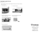
No
1
2
3
4
5
6
7
8
9
Function
Auto Iris lens connector
Video out
Power Terminal (It is already connected. Follow
Steps 11 to 12 in
Installing Camera Module
to
insert the Power Cable.)
Moves down the OSD menu.
Moves the focus rightward to select menu options.
Power LED
Moves up the OSD menu.
Enters the OSD menu option and confirms the
selection
Moves the focus leftward to select menu options.
See the lists below for shutter speed settings.
1
2
165 SEC
182 SEC
183 (*) SEC
184 SEC
185 SEC
225 SEC
Distance between the object and the
camera is 550 cm (18.04 ft).
Notes:
1. The default settings are marked with (*).
2. The gray areas in the charts are not recommended for use.
145 SEC
150 SEC
155 SEC
170 SEC
180 SEC
200 SEC
Distance between the object and the
camera is 1100 cm (36.08 ft).
1
2
3
4
5
6
7
8
SW2
ON
ON
ON
ON
OFF
OFF
OFF
OFF
LED Brightness (mA)
470 (Default Setting)
400
350
300
250
200
150
100
Note: The factory default GAMMA value is set to be 1. It will be adjusted to 0.45 every time when you select
RESET. For optimal image performance, it is recommended to adjust the GAMMA value to 1.
SW3
ON
ON
OFF
OFF
ON
ON
OFF
OFF
SW4
ON
OFF
ON
OFF
ON
OFF
ON
OFF