


5.2.1 Defining Readers on GV-AS Controller Web Interface
Since multiple readers can connect to GV-AS Controller using one RS-485 interface, you
need to specify which door each reader controls. This section explains how to define readers
on the Web interface of GV-AS Controller using
GV-AS210 Controller
as an example.
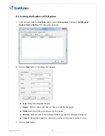
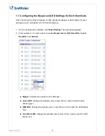
1. On the GV-AS210 Web interface, click
Extended Reader
. This dialog box appears.
2. In the GV-Reader/CR420/GF1921/GF1922 section, select the
RS485
checkbox in front of
the ID number and type the
Serial Number
on the rear panel of the reader. The ID
number will be assigned to the reader.
3. Select a door/gate for the reader from the
Function
drop-down list. Click
Submit
.
April 24, 2014
4
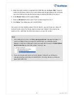
Note:
When you click
Submit
on the Extended Reader page of a GV-AS210 / 410 / 810,
all GV-RK1352 / R1352 / DFR1352 connected through RS-485 interface will reboot.