


13
12
GV-Data Capture
GV-Data Capture
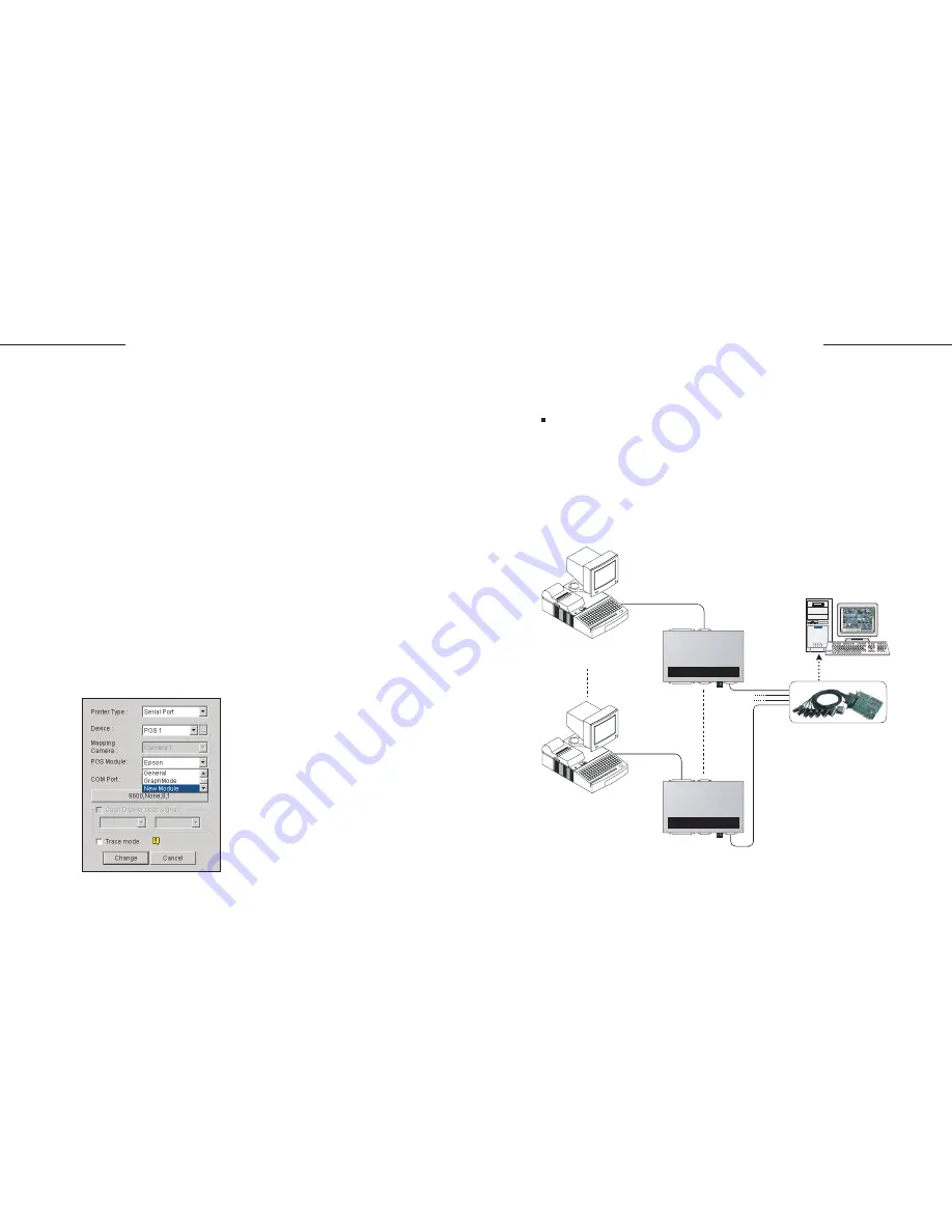
Normally, one PC comes with 2 COM ports, therefore only 2 POS
systems/cash registers may be supported without COM port extension. The
extension is made possible by adding
Moxa
extension modules, such as N
Port 1240, C218 Turbo Series, Industrio CP-114 Series and C320 Turbo
Multiport. The following diagram illustrates how a Turbo Series card can be
connected with one GV-system and four POS systems.
1.
2.
3.
4.
5.
6.
7.
8.
In the Select Base Printer Command field, select the printer command
used by your POS system or cash register.
In the Transaction Void field, enter the exact transaction text used to
identify "void". For this example, look at the receipt and we find the exact
text is ITEM VOID.
In the Transaction Stop field, enter the stop command used by your
printer. If your printer does not support the Form Feed or CutPaper
command, enter the exact transaction text used to identify "stop". For this
example, **********17:34***05/03/04********** indicates the transaction
stop. However, since the time and date varies with each transaction, only
enter ********** as the stop command.
In the New POS Module Name field, enter a module name for the new
settings.
Click
Go
to apply all settings.
Run POS Server Setup. (GV-system/Configure/POS Application
Setting/POS Device Setup)
Click the
New
button in the POS Server Setup window.
In the POS Module drop-down list, select the POS module you created in
TranStopEdit.
Connecting more than 2 POS systems/cash registers
Figure 5. Selecting the created POS module
GV-System
POS Device 1
POS Device 4
RS-232
Parallel port
RS-232
RS-232
RS-232
C218 Turbo Series
GeoVision GV-DATA CAPTURE
GeoVision GV-DATA CAPTURE
9. Click
Add
, and test this setting.
Summary of Contents for DCV1-A-EN
Page 1: ...2005 01 GV Data Capture...