


7
6
GV-Data Capture
GV-Data Capture
5. After above settings, click
Add
to add the POS system to the GV-system.
Trace Mode:
Check this option only after getting the recommendation
from our technical support staff.
2. Run the GV-system.
3. Click the
Configure
button, point to
POS Application Setting
, and select
POS Device Setup
. This displays the POS Server Setup dialog box.
4. All settings are the same as previously discussed in the
Serial POS
System
section, except that for
Printer Type
and
Baud Rate
.
5. Click
Add
to apply the settings.
6. Adjust the DIP switch settings in the Capture box from Serial Port to
Parallel Port, as illustrated below:
The two precautions taken when connecting the parallel POS system will
help ensure trouble-free operation.
Follow these steps to make the connection:
Make sure to connect a receipt printer or a terminator to the Capture box
(See the illustration below), or the GV-system cannot receive any
transaction data.
Make sure to restart your POS system after connecting the Capture box.
Parallel POS System
1. Connect the GV-Data Capture box as illustrated below:
The Parallel cable , the RS-232 cable , and Terminator supplied with
the GV-Data Capture box.
The Parallel cable supplied with the POS system.
2
1
3
DB25
Female
DB25 Male
Terminator
or
GV-System
POS System
DB25
Male
DB9 Female
DB9 Male
DB25 Female
Printer
RS-232
2
Parallel
3
Parallel
1
GeoVision GV-DATA CAPTURE
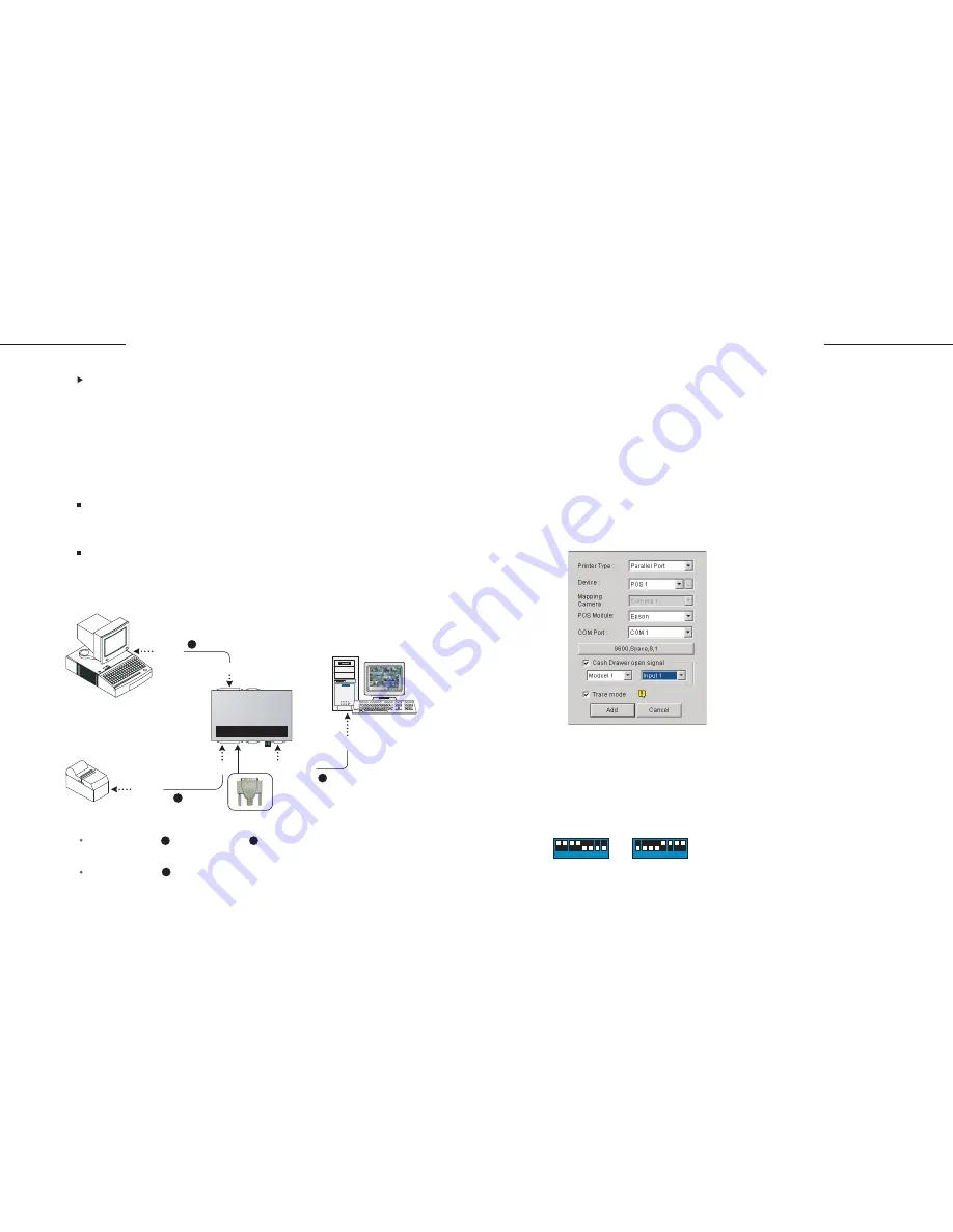
A.
Select
Parallel Port
in the Printer Type field.
B.
Clicking the parameter button, you will find only the Baud Rate item is available.
Keep it in default.
1 2 3 4 5 6 7 8
1 2 3 4 5 6 7 8
Parallel Port
Serial Port (default)
Figure 2. Parallel POS System settings
Summary of Contents for DCV1-A-EN
Page 1: ...2005 01 GV Data Capture...


