GeoSmart Premium G Installation Information Download Page 13

13

In ground water situations where scaling could be heavy or where 
biological growth such as iron bacteria will be present, a closed 
loop system is recommended. The heat exchanger coils in ground 
water systems may, over a period of time, lose heat exchange 
capabilities due to a buildup of mineral deposits inside. These 
can be cleaned, but only by a qualified service mechanic, as 
special solutions and pumping equipment are required. Hot water 
generator coils can likewise become scaled and possibly plugged. 

Water Quality

Material

Copper

90/10 Cupronickel

316 Stainless Steel

pH

Acidity/Alkalinity

7 - 9

7 - 9

7 - 9

Scaling

Calcium and

Magnesium Carbonate

(Total Hardness)

less than 350 ppm

(Total Hardness)

less than 350 ppm

(Total Hardness)

less than 350 ppm

Corrosion

Hydrogen Sulfide

Less than 0.5 ppm (rotten egg 

smell appears at 0.5 ppm)

10 - 50 ppm

Less than 1 ppm

Sulfates

Less than 125 ppm

Less than 125 ppm

Less than 200 ppm

Chlorine

Less than 0.5 ppm

Less than 0.5 ppm

Less than 0.5 ppm

Chlorides

Less than 20 ppm

Less than 125 ppm

Less than 300 ppm

Carbon Dioxide

Less than 50 ppm

10 - 50 ppm

10 - 50 ppm

Ammonia

Less than 2 ppm

Less than 2 ppm

Less than 20 ppm

Ammonia Chloride

Less than 0.5 ppm

Less than 0.5 ppm

Less than 0.5 ppm

Ammonia Nitrate

Less than 0.5 ppm

Less than 0.5 ppm

Less than 0.5 ppm

Ammonia Hydroxide

Less than 0.5 ppm

Less than 0.5 ppm

Less than 0.5 ppm

Ammonia Sulfate

Less than 0.5 ppm

Less than 0.5 ppm

Less than 0.5 ppm

Total Dissolved Solids (TDS)

Less than 1000 ppm

1000 - 1500 ppm

1000 - 1500 ppm

LSI Index

+0.5 to -0.5

+0.5 to -0.5

+0.5 to -0.5

Iron Fouling

(Biological Growth)

Iron, FE

2

+ (Ferrous)

Bacterial Iron Potential

< 0.2 ppm

< 0.2 ppm

< 0.2 ppm

Iron Oxide

Less than 1 ppm, above this level 

deposition will occur

Less than 1 ppm, above this level 

deposition will occur

Less than 1 ppm, above this level 

deposition will occur

Erosion

Suspended Solids

Less than 10 ppm and filtered for 

max. of 600 micron size

Less than 10 ppm and filtered for 

max. of 600 micron size

Less than 10 ppm and filtered for 

max. of 600 micron size

Threshold Velocity

(Fresh Water)

< 6 ft/sec

< 6 ft/sec

< 6 ft/sec

NOTES:

  Grains = ppm divided by 17

mg/L is equivalent to ppm

2/22/12

In areas with extremely hard water, the owner should be informed 
that the heat exchanger may require occasional flushing. Failure 
to adhere to the guidelines in the water quality table could result in 
loss of warranty.

Units with cupronickel heat exchangers are recommended for open 
loop applications due to the increased resistance to build-up and 
corrosion, along with reduced wear caused by acid cleaning.

System Cleaning and Flushing

Cleaning and Flushing

Prior to start up of any heat pump, the water circulating system 
must be cleaned and flushed of all dirt and debris.

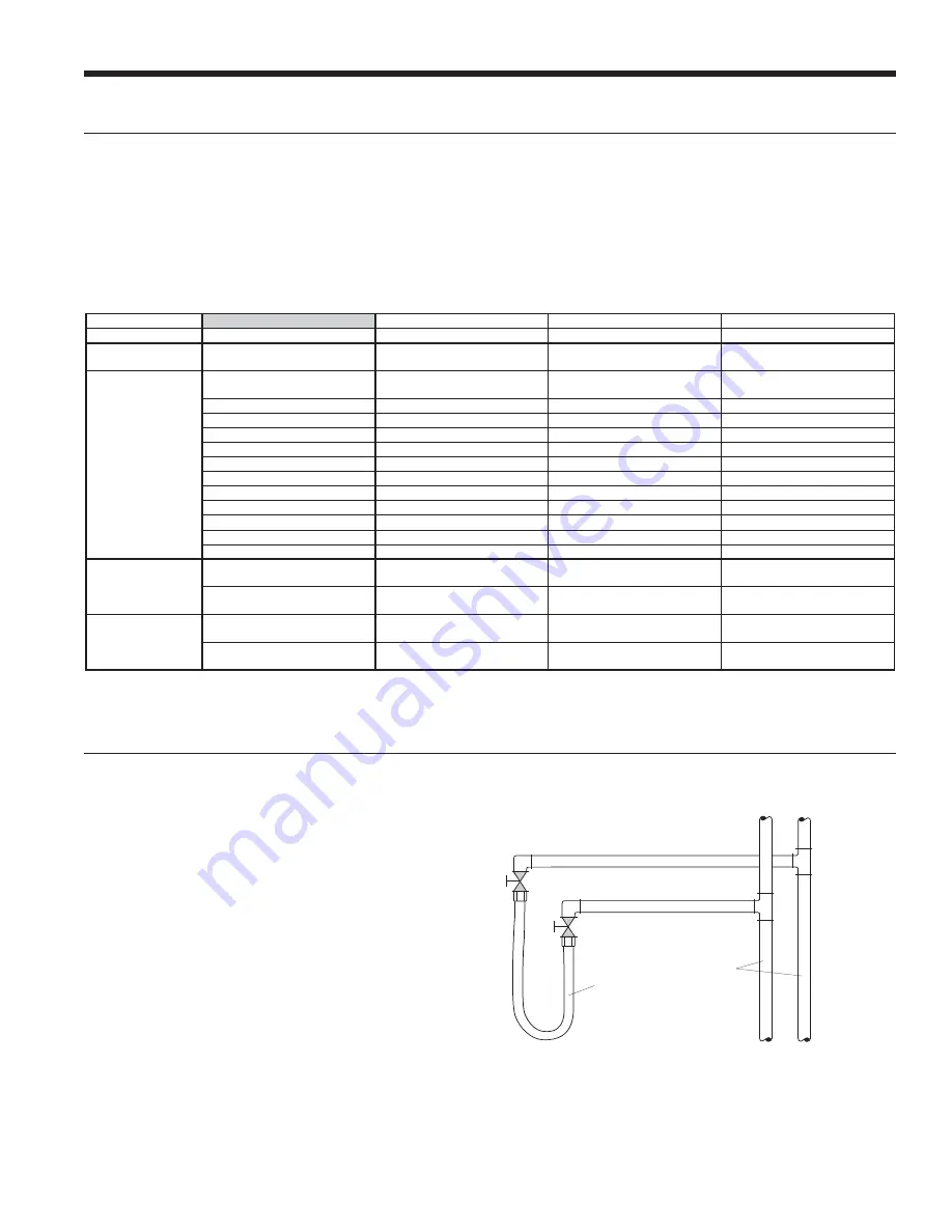
If the system is equipped with water shutoff valves, the supply and 
return runouts must be connected together at each unit location 
(This will prevent the introduction of dirt into the unit,  see Flushing 
with Water Shutoff Valve Equipped Systems illustration). The 
system should be filled at the water make-up connection with all air 
vents open.  After filling, vents should be closed.

The contractor should start the main circulator with the pressure 
reducing valve makeup open. Vents should be checked in 
sequence to bleed off any trapped air and to verify circulation 
through all components of the system.

As water circulates through the system, the contractor should 
check and repair any leaks found in the piping system. Drain(s) at 
the lowest point(s) in the system should be opened for initial flush 
and blowdown, making sure water fill valves are set at the same 
rate. Check the pressure gauge at the pump suction and manually 

Return Runout

Supply Runout

Mains

Rubber Hose

Runouts Initially
Connected Together

Flushing with Water Shutoff Valve Equipped Systems

PREMIUM G COMPACT INSTALLATION MANUAL

Summary of Contents for Premium G

Page 1: ...L Installation Information Water Piping Connections Electrical Startup Procedures Troubleshooting Preventative Maintenance Premium Compact Forced Air Geothermal Comfort System Geothermal Heat Pumps R...

Page 2: ......

Page 3: ...r Connections 15 Freeze Detection 17 Electrical Connections 17 Electrical Data 18 Blower Performance Data 21 Wiring Schematics 26 Controls 28 Unit Startup 32 Operating Limits 33 Operating Parameters 3...

Page 4: ...072 Water Coil Option C Copper D Insulated Copper N CuproNickel P Insulated CuproNickel Vintage Factory Use Only Non Standard Options SS Standard Drain Pan Option 0 Composite No Secondary Connection...

Page 5: ...ving the units from the packaging if necessary Units in question should also be internally inspected If any damage is noted the carrier should make the proper notation on the delivery receipt acknowle...

Page 6: ...pen return applications Deluxe filter rack for ductable return applications 2 61 cm Service Access Left Return Right Return opposite side 2 61 cm Alternate Service Access Field installed duct flange A...

Page 7: ...lter rack 0 10 in M N P Q R S T U V W Filter Rack Width Supply Width Supply Depth Return Depth Return Height 009 012 in 2 2 10 0 10 0 6 1 5 3 9 8 2 0 18 1 14 0 2 0 cm 5 6 25 4 25 4 15 5 13 5 24 9 5 1...

Page 8: ...AIR COIL SIDE 0 5 in 1 3 cm knockout 1 in 2 5 cm knockout 1 in 2 5 cm knockout 0 5 in 1 3 cm knockout BP BP FILTER RACK FILTER RACK Standard filter rails Standard filter rails Deluxe filter rack opti...

Page 9: ...Supply Depth Return Depth Return Height 009 012 in 5 9 7 2 9 5 6 0 16 4 14 5 2 0 1 4 3 4 cm 15 0 18 3 24 1 15 2 41 7 36 8 5 1 3 6 1 9 015 018 in 6 7 10 5 9 4 4 9 27 4 16 6 2 0 1 4 3 4 cm 17 0 26 7 23...

Page 10: ...ow filter access install hanger brackets as illustrated in the Hanger Bracket Locations section The unit should be pitched approximately 1 4 in towards the drain in both directions to facilitate the r...

Page 11: ...99S500A04 45 8 25 1 21 4 n a cm 116 3 63 8 54 4 n a 038 in 99S500A03 48 8 28 1 24 4 n a cm 124 0 71 4 62 0 n a 049 in 99S500A04 53 8 28 1 24 4 n a cm 136 7 71 4 62 0 n a 064 in 99S500A04 61 8 28 1 24...

Page 12: ...ure proper flow use pressure temperature ports to determine the flow rate These ports should be located at the supply and return water connections on the unit The proper flow rate cannot be accurately...

Page 13: ...deposition will occur Erosion Suspended Solids Less than 10 ppm and filtered for max of 600 micron size Less than 10 ppm and filtered for max of 600 micron size Less than 10 ppm and filtered for max o...

Page 14: ...alkaline pH 7 5 to 8 5 The specified percentage of antifreeze may also be added at this time Use commercial grade antifreeze designed for HVAC systems only Environol brand antifreeze is recommended On...

Page 15: ...the water heater tank 4 Drain the tank by opening the valve on the bottom of the tank then open the pressure relief valve or hot water faucet 5 Flush the tank by opening the cold water inlet valve to...

Page 16: ...t the temperature setting on the tank On tanks with both upper and lower elements the lower element should be turned down to the lowest setting approximately 100 F The upper element should be adjusted...

Page 17: ...rdance with local codes or the National Electric Code whichever is applicable Power Connection Connect the incoming line voltage wires to L1 and L2 of the con tactor for single phase unit Consult the...

Page 18: ...208 230 60 3 187 253 13 9 8 9 58 0 34 8 2 8 11 7 13 9 20 460 60 3 414 506 6 5 4 2 28 0 16 8 1 4 5 6 6 7 10 15 036 208 230 60 1 187 253 22 0 14 1 73 0 29 2 3 5 17 6 21 1 35 265 60 1 238 292 17 5 11 2...

Page 19: ...21 2 13 6 83 1 49 9 7 6 21 2 24 6 35 460 60 3 414 506 9 5 6 1 41 0 24 6 4 0 10 1 11 6 15 060 208 230 60 1 187 253 41 2 26 4 134 0 53 6 7 6 34 0 40 6 60 208 230 60 3 187 253 24 9 16 0 110 0 66 0 7 6 2...

Page 20: ...0 30 460 60 3 414 506 9 5 6 1 41 0 24 6 4 1 10 2 11 7 15 048 208 230 60 1 187 253 31 0 19 9 109 0 43 6 7 0 26 9 31 9 50 208 230 60 3 187 253 21 2 13 6 83 1 49 9 7 0 20 6 24 0 35 460 60 3 414 506 9 5...

Page 21: ...2140 2095 2045 1945 1835 1715 1510 1330 M 2265 2235 2205 2175 2145 2110 2070 2035 2000 1960 1915 1825 1730 1605 1440 1260 L 2075 2050 2020 1995 1965 1940 1915 1885 1850 1820 1785 1720 1610 1505 1335 1...

Page 22: ...520 495 455 420 400 030 High 5 9 x 7 1 2 1407 1381 1354 1327 1300 1267 1233 1201 1168 1131 1094 1009 Med High 4 W 1146 1134 1122 1111 1099 1085 1071 1062 1052 1042 1031 966 Med 3 Y1 1023 1012 1001 98...

Page 23: ...9 1780 1760 1747 1734 1700 1659 1617 Med High 4 1799 1783 1767 1744 1720 1693 1666 1649 1631 1617 1603 1560 1530 1492 Med 3 Y2 1694 1680 1666 1642 1617 1592 1567 1552 1537 1519 1500 1453 1421 1372 Med...

Page 24: ...100 1300 1500 1750 1950 2100 2300 L M H 070 0 75 11 x 10 1 800 950 1100 1300 1500 1750 1950 2100 2300 L M H 3 16 12 Dual Capacity Model Max ESP Blower Size Motor hp Air Flow DIP Switch Settings 1 2 3...

Page 25: ...een displays the current variable speed ECM settings It allows the technician to enter the setup screens to change the variable speed ECM settings Change the highlighted item using the and buttons and...

Page 26: ...lower Off Delay Fault Recognition Delay High Pressure Start Up Bypass Low Pressure Fault Recognition Delay Low Pressure Start Up Bypass Low Water Air Coil Limit Fault Recognition Delay Low Water Air C...

Page 27: ...stalled 5 Wire is provided with the unit but only connected to the X13 motor on dual capacity units Notes Accessory Relay Cycle with Blower Cycle with Compressor Water Valve Slow Open Outdoor Air Damp...

Page 28: ...ne time Test mode will automatically time out after 30 minutes Test mode can be exited by pressing and holding the SW1 button for 2 to 5 seconds or by cycling the power NOTE Test mode will automatical...

Page 29: ...d shall flash the fault code To reset lockout conditions with SW2 8 On thermostat inputs Y1 Y2 and W must be removed for at least 3 seconds To reset lockout conditions with SW2 8 Off thermostat inputs...

Page 30: ...command is removed Regardless of blower input G from the thermostat the blower will remain on for 30 seconds at the end of each heating cycle Cooling Operation In all cooling operations the reversing...

Page 31: ...plugs into the exterior of the cabinet in the AID Tool port ABC Control Board Layout Aurora Base Control LED Displays These three LEDs display the status configuration and fault codes for the control...

Page 32: ...ure drop through the heat exchanger using the P T plugs and comparing to the pressure drop table 6 Check the temperature of both the supply and discharge water Refer to Operating Parameters tables 7 C...

Page 33: ...psig Discharge Pres sure psig Superheat Subcooling Water Temp Rise F Air Temp Drop F DB 30 1 5 115 125 150 170 20 35 10 17 17 22 17 23 3 0 105 120 130 145 20 35 10 17 8 10 17 23 50 1 5 130 140 215 235...

Page 34: ...eratures of 80 F DB 67 F WB Heating performance based on entering air temperature of 70 F DB 2 15 12 Second Stage Operation Entering Water Temp F Water Flow gpm ton Cooling No Hot Water Generation Suc...

Page 35: ...5 3 3 11 0 17 2 0 41 14 0 7 6 6 7 6 3 5 8 5 4 14 0 17 9 0 61 048 6 0 1 1 1 0 1 0 0 9 0 8 1 in 6 0 16 1 0 14 9 0 2 3 2 1 2 0 1 9 1 7 9 0 16 8 0 29 12 0 3 9 3 7 3 4 3 2 3 0 12 0 17 4 0 47 16 0 6 7 6 3 5...

Page 36: ...alves Low High Low High Normal High Low Low TXV Bulb Loss of Charge Low Low Low High High Low Low Scaled Coaxial Heat Exchanger Heating Low Low Low Normal Low High Low Low Scaled Coaxial Heat Exchange...

Page 37: ...a 0 96 1 10 3 88 4 46 5 88 6 76 060 0 42 0 48 0 73 0 85 n a 0 63 0 73 2 98 3 42 4 96 5 70 070 0 33 0 39 0 90 1 04 n a 0 56 0 64 2 34 2 70 3 48 4 00 Dual Capacity 026 1 21 1 39 1 52 1 75 1 38 1 58 2 0...

Page 38: ...5 83 0 15 0 37 9 53 7 69 8 82 9 83 4 91 2 89 4 82 7 76 8 18 0 38 1 54 3 70 9 84 8 83 8 91 9 90 3 83 6 77 6 3 16 12 Dual Capacity Model gpm Heat of Extraction HE MBtu h Heat of Rejection HR MBtu h 30...

Page 39: ...ration is noisy 1 Check compressor for loosened mounting bolts Make sure compressor is floating free on its isolator mounts Check for tubing contact with the compressor or other surfaces Readjust it b...

Page 40: ..._ AMPS n ______ AMPS Watts m x n x 0 85 o _____ WATTS o ______ WATTS 6 CAPACITY Cooling Capacity HR o x 3 413 p _____ btu hr Heating Capacity HE o x 3 413 p _____ btu hr 7 EFFICIENCY Cooling EER p o q...

Page 41: ...tage Loop Open Unit Amp Draw Closed COAX SOURCE HEA7 1 ANALYSIS EXPANSION VALVE F AIR COIL F COMPRESSOR DISCHARGE SUCTION Subcooling Superheat REVERSING VALVE PSI F SAT F PSI SAT F F F LIQUID LINE Lin...

Page 42: ...te Drain In areas where airborne bacteria produce a slime in the drain pan it may be necessary to treat chemically to minimize the problem The condensate drain can pick up lint and dirt especially wit...

Page 43: ...Available 5 Speed ECM Motor Blower 5 Spd ECM Motor 208 230 60 1 Not Available 14P536 01 14P537 01 5 Spd ECM Motor 265 60 1 Not Available 14P536 02 14P537 02 5 Spd ECM Motor 230 60 3 Not Available 14P5...

Page 44: ...02 14S553 02 Not Available 5 Speed ECM Motor Blower 5 Spd ECM Motor 208 230 60 1 Not Available 14P536 01 14P537 01 5 Spd ECM Motor 265 60 1 Not Available 14P536 02 14P537 02 5 Spd ECM Motor 230 60 3...

Page 45: ...le Not Available 14S553 01 14S553 01 Not Available High Static VS ECM Motor 460 60 3 Not Available 14S553 02 14S553 02 Not Available Not Available 14S553 02 14S553 02 Not Available 5 Speed ECM Motor B...

Page 46: ...46 Notes PREMIUM G COMPACT INSTALLATION MANUAL...

Page 47: ...47 Revision Guide PREMIUM G COMPACT INSTALLATION MANUAL Pages Description Date By All Updated with All Aluminum Air Coils 19 May 2014 DS All First Published 13 Sept 2013 DS...

Page 48: ...tem Size 75 6 Ton Single Stage 2 6 Ton Two Stage Document Type Installation Manual Ref Number IM1022AG2 Revision Date 05 14 Revision Number Document Name TEC IOM GB 0514v1 650 Jamieson Parkway Unit 1...

Reviews: