background image

29

EM61LX2 Data Logging System (DAS70-AR2)

7.  Logging Data

After the 

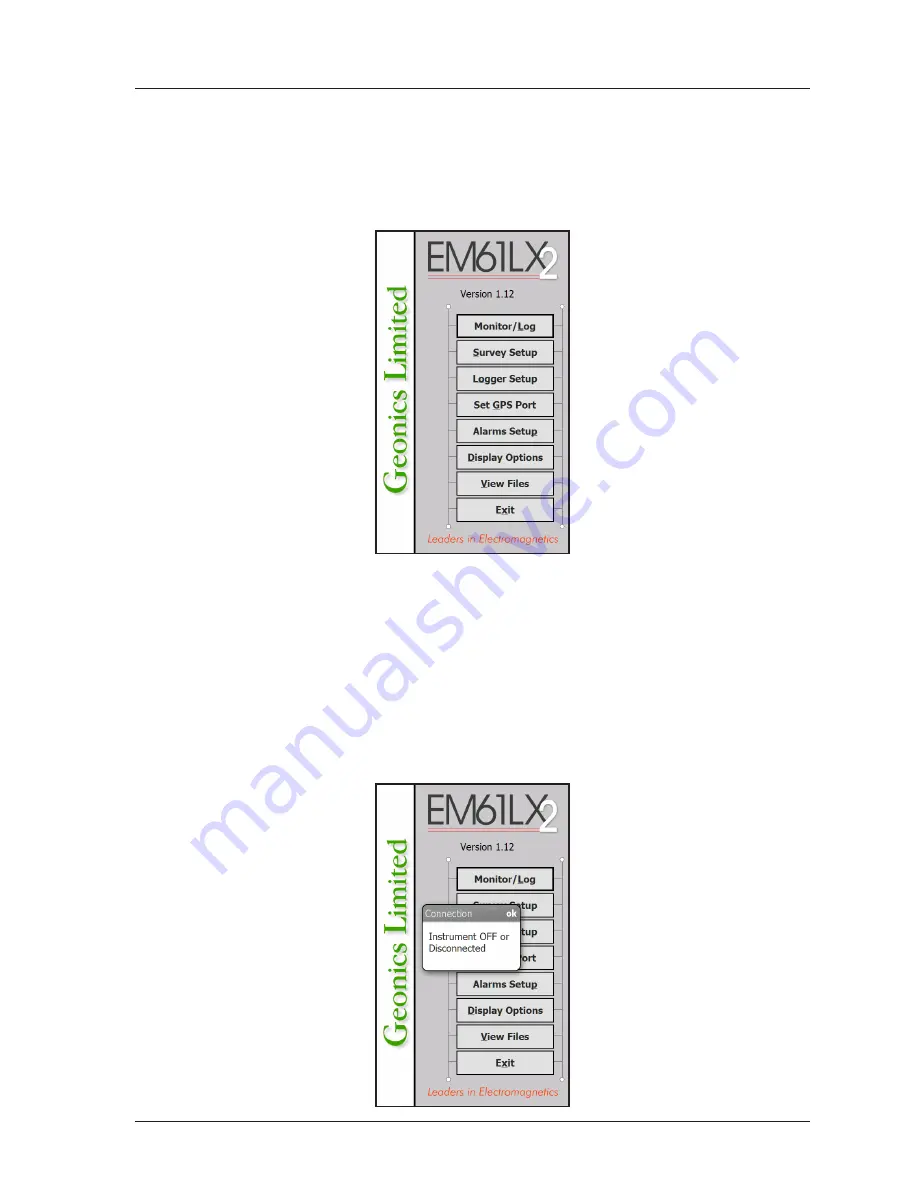
Monitor/Log

 button (in Main Screen) is tapped or executed by the keyboard, the program enters 

logging session which contains three modes: Monitoring, Stand By and Logging. Program starts logging 

session always in Monitoring mode. In this mode EM61-LX2 readings and GPS parameters can be quickly 

examined and some functions (creating data file, nuling) can be performed. After a data file is created in 

Monitoring mode, the program switches to Stand By mode and allows access to Logging mode. In Stand 

By mode instrument output can be monitored and some survey and logging parameters can be changed, 

and Logging mode is used only to record data. Two modes Stand By and Logging are toggled by 

GO

 and 

Pause

 buttons.   

7.1   Monitoring Mode

The Monitor mode allows initial inspection of the range of the instrument readings at a particular 

site, monitoring the instrument performance, quick inspection of the condition of the instrument 

battery, reading scale, display mode, and setting zero level of the instrument.

Summary of Contents for EM61LX2

Page 1: ...e Drive Mississauga Ontario Canada L5T 1C6 Tel 905 670 9580 Fax 905 670 9204 E mail geonics geonics com Geonics Limited June 2020 Version 1 16 EM61LX2 DATA LOGGING SYSTEM FOR FIELD COMPUTER ARCHER2 OP...

Page 2: ......

Page 3: ...3 Logger Setup 11 3 1 Description of Parameters 11 3 2 Bluetooth Connection of EM61 LX2 and Archer2 13 4 Set Port for GPS 17 4 1 Monitoring GPS Receiver Output 19 5 Alarms Setup 21 6 Display Options...

Page 4: ......

Page 5: ...arly ChLL Left Late and similarly for the right sensor ChRE Right Early and ChRL Right Late It is always assumed that the left sensor is on the left and the right one on right of center point while fa...

Page 6: ...k that the file EM61LX2wm is included in Archer directory on the CD disk 1 2 Installing EM61LX2 While using the Archer the EM61LX2wm exe file should be transferred from a desktop PC using MS Central P...

Page 7: ...rcher2 user manual 1 3 Data Files Transfer Data files are saved in the Allegro with extension L61 Transfer of files to desktop PC can be per formed with MS Central Point Windows 7 8 10 MS ActiveSync W...

Page 8: ...ialog windows are given in the form of text boxes and drop down boxes which can be accessed using touchscreen or by the keyboard Each dialog window has a title bar with a caption describing the dialog...

Page 9: ...and External QC coil calibration monitoring EM61 LX2 and Archer2 battery level etc Survey Setup The Survey Setup dialog will be displayed All survey settings survey line name increments etc can be sp...

Page 10: ...colour and thickness of profile lines will appear This dialog provides also choice of linear or compressed amplitude used for profile display View Files This option allows to review data files saved...

Page 11: ...is logged 10 readings s will cause the program to log at a rate of 9 readings s ev ery second reading from instrument output is logged etc At slower rates the difference between specified and effecti...

Page 12: ...ring field surveys One Way is used when each survey line is traversed in the same direction The choice of this parameter will affect the default start station a signature of the station increment and...

Page 13: ...ncrement This parameter specifies the station increment for the selected survey line This value is used in conjunction with Start Station to calculate the current station number for display purposes A...

Page 14: ......

Page 15: ...ogger Setup dialog is presented below 3 1 Description of Parameters EM61LX2 Port The number of serial port that is assigned to the EM61 LX2 Available selections COM1 to COM12 The program default is CO...

Page 16: ...ks the exactly same way as physical cable connection assuming that proper serial port COMx is selected To check which serial port COM is assigned for Bluetooth communication select Settings from Start...

Page 17: ...e selected the sensor number 1 is the one located on the left and sensor number two is located on the right while facing both antennas in the direction of movement When one sensor is selected then it...

Page 18: ...urn to the Main Screen Updated settings will be written to the initial file and they will be given as default parameters in the subsequent Log ger Setup dialog To return to original settings state bef...

Page 19: ...rmal operation press the Next again and after few seconds a dialog confirming addition of the EM61 LX2 Bluetooth will be displayed see the Figure below Tap the Yes button to confirm and a screen promp...

Page 20: ...forget to tap on the Serial Port check button see two Figures below Tap on the Save label and the display will return to a list of available Bluetooth devices with updated name of the EM61 LX2 device...

Page 21: ...ile will contain proper sequence of EM61 LX2 readings without any GPS input Tapping on the down arrow next to the text box labeled GPS Input opens a drop down box showing the available settings or whe...

Page 22: ...s N Tapping on the down arrow next to the text box labeled Parity opens a drop down box showing the available parameters or when the keyboard is used activate this text box by pressing TAB key and the...

Page 23: ...mode In this mode the screen is divided into three parts The larg est top portion of the screen displays the GPS receiver output The middle portion shows that last NMEA command sent to the GPS receiv...

Page 24: ...you to send a NMEA command to the GPS receiver It is preferable if the GPS receiver parameters are set using the GPS manufacturer software or controller GPS logger or panel keys However when the oper...

Page 25: ...ver one of sensor is triggered Description of Options and Parameters Alarm Type This option allows you to selected one of three settings for alarm Disabled Simple and Enhanced Tapping on the down arro...

Page 26: ...arm only Specify amplitude value that will trigger alarm Whenever the target response will be larger than specified amplitude the alarm will be triggered Visual alarm will be always displayed while an...

Page 27: ...ate 9 Hz requires 5 samples Tapping on the down arrow next to the text box labeled Med Widthopens a drop down box showing the available parameters or when the keyboard is used activate this text box b...

Page 28: ...parameters in the Set Output Port dialog are updated tap the button OK or press ENTER key to accept the displayed settings The program will return to the Main Screen Updated settings will be written...

Page 29: ...olour line labeled Color The standard dialog titled Color will appear Select desired colour by tapping on a colour box the selected colour box will be highlighted Tap the button OK or press ENTER key...

Page 30: ...are selected for profile display the selected here channel will be monitored by alarm func tions When ChF is selected for profile display then alarm always monitors ChF Tapping on the down arrow next...

Page 31: ...s The program will return to the Main Screen Updated settings will be written to the initial file and they will be given as default parameters in the subsequent Survey Setup dialog To return to origin...

Page 32: ......

Page 33: ...fter a data file is created in Monitoring mode the program switches to Stand By mode and allows access to Logging mode In Stand By mode instrument output can be monitored and some survey and logging p...

Page 34: ...dow and will start normalization session which lasts less than 10 seconds At this stage the Monitor window will display the following message After the normalization is finished the layout of the Moni...

Page 35: ...or as well as Stand by and Logging window is divided into four sections in each graphic mode Three lines of text in vertical screen layout in the top section provides survey parameters used in Stand B...

Page 36: ...d Position Dilution of Precision PDOP This value is available only when messages both GGA and GSA are received from GPS The last label Sat and following number shows number of currently tracked satell...

Page 37: ...mode automatically The log file can be created in the default folder My Documents DATA61LX2 in the Archer2 The name of the file is given by the field computer clock and it consists of month 2 digits...

Page 38: ...s key U At this moment the computer takes 50 readings and calculates the instrument offset The calculated offset is applied to all the readings that follow this operation If needed this procedure can...

Page 39: ...the bottom right and top right corners of the plot area or at the colour bar in the Modulated Ribbon graphic mode After minimum and maximum values are specified tap the button OK or press ENTER key t...

Page 40: ...dow appears on the screen The dialog is presented below Please refer to chapter 5 where this dialog and its parameters are described in detail Tap the button OK or press ENTER key to accept updated di...

Page 41: ...n Monitoring mode the program automatically switches logging window to Stand By mode This windows is similar to Monitor mode however it contains survey parameters file name survey line name etc additi...

Page 42: ...ion labeled Stn and EM61 LX2 battery level in Volts labeled B When fiducial marker is active a label M is displayed between station label and station value In the Stand By mode the station number will...

Page 43: ...re described in the preceding section 7 2 The screen in Logging mode is presented below please note red highlighted background for channels LE and LL that indicates Alarm for Left Sensor After the scr...

Page 44: ...are exactly the same as described in Monitoring mode options please refer to section 7 1 New options in the Stand By mode are GO Line New Station and Comment The Nulling procedure has additional prom...

Page 45: ...yed settings The program will return to the Logging window in Stand By mode Survey line Ln name and current station Stn value will be updated and profile curves plot for former survey line will disapp...

Page 46: ...e file with a corresponding time stamp and the program will return to the Logging window in Stand By mode To ignore an entry and return to Stand By mode tap Cancel X button or press Esc key the dialog...

Page 47: ...a collection in Stand By mode a confirmation message will be displayed there is no such message if Exit is performed in Monitoring mode before program exits logging window After above message is confi...

Page 48: ......

Page 49: ...te to the button by pressing TAB key and when highlighted press ENTER key or use shortcut press key F The Open Data File dialog is presented below The file name can be selected in the Open Data File d...

Page 50: ...the button labeled Scale The plot area is divided by four or five grey grid lines In cases where the amplitude scale starts with a negative value then the grid line corresponding to zero is always plo...

Page 51: ...s and to move the vertical bar indicating the currently displayed station use the buttons located along the bottom of the View Files window These but tons can be activated by tapping or by pressing th...

Page 52: ...adings button labeled or key Left left arrow moves vertical bar station one station to the left button labeled or key Right right arrow moves vertical bar station one station to the right To exit the...

Reviews: