Geometrics SmartSeis Maintenance Manual Download Page 14

SmartSeis

TM

 Maintenance Manual 


14


3.  Disconnect the power distribution cable from connector J7, the 10-pin ribbon cable 

located on the left and top side of the board (Figure 4).   

4.  Disconnect the ribbon cables from the OMNI board noting their locations as discussed 

above. 

5.  Carefully and gently ease the OMNI board loose from its backplane slot; slide it out of 

the slotted card guide that is integrated into the right-hand-side of the chassis (Figure 4) 
with even pressure on both sides; continue to remove the board. 

A board installation is the reverse of a removal.  Before installing a new board, you must check 
that the jumpers are properly set (see 

Section 2.3.1, OMNI board jumper settings

).  When 

reconnecting the ribbon cables, be very careful so that you do not bend the connector pins or 
nearby parts.  Also, each replaced board needs to be fully seated into its backplane slot, 
reslotted into the bracket, and squarely aligned with the chassis and the other boards.   

As mentioned above, we suggest that you turn the seismograph on and confirm that it is 
functioning properly after the repair and before reinstalling the seismograph in its case.  To 
confirm that the OMNI board is performing, check the functionality of all the associated 
components listed in Table 2.  


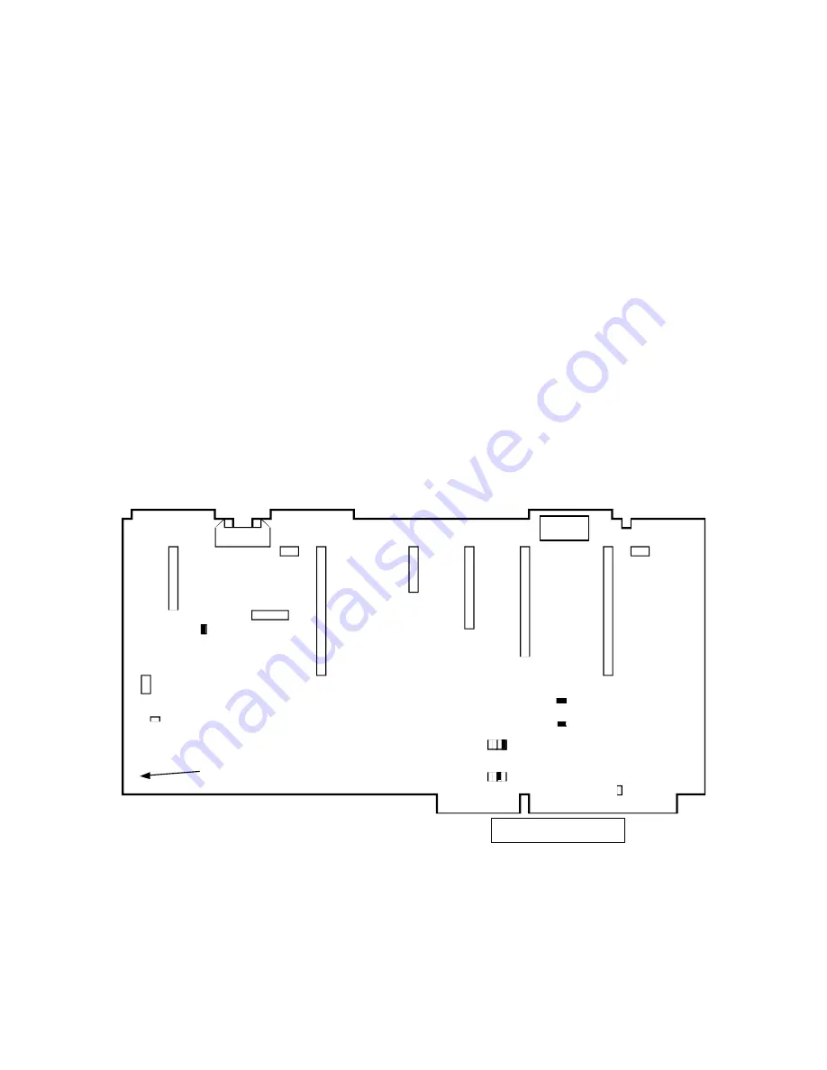
Figure 4. Diagram of an OMNI board (top view).


J-numbered ports connect to ribbon cables 

terminated with appropriate connectors (Table 2) and the JP-numbered jumper pins are 
connected with jumpers, see 

Section 2.3.1, OMNI board jumper settings

, for board-specific 

settings.  The S1 switches set the VGA panel configuration. 


JP3

JP6

J1

J2

J3

J4

J5

J6

J7

JP7

JP10

J8

J9

J10

S1

JP2

JP13

JP12

JP1

Trigger Cable

JP11


ISA edge connectors


LEDs 

This corner 

slides into card 

guide slot 

BACK 

FRONT 

Summary of Contents for SmartSeis

Page 1: ...SmartSeisTM Maintenance Manual Geometrics Inc 2190 Fortune Drive San Jose CA 95131 Tel 408 954 0522 Fax 408 954 0902 Email sales mail geometrics com Internet www geometrics com...

Page 2: ...1 Software 5 1 4 2 Hardware 6 2 0 SmartSeisTM Maintenance and Repair 9 2 1 Internal seismograph access 9 2 2 Replacing an acquisition board 10 2 2 1 Acquistion board jumper settings 11 2 3 Replacing t...

Page 3: ...t the DOS prompt then press ENTER 1 1 External power The most common problem is power failure normally a discharged battery The front panel has a series of lights which constantly display the battery...

Page 4: ...eck the cable connections starting with the panel connector s leading to the acquisition board s You can try swapping the connections to the acquisition boards if you have a 24 channel system If the p...

Page 5: ...ed If false triggering persists it may be necessary to add external attenuation or isolation to correct the problem 1 4 Internal system 1 4 1 Software Since the SmartSeisTM is a normal PC compatible s...

Page 6: ...ing the sun and is corrected when moved away and allowed to cool Storage devices Most problems with the floppy and hard drives will be indicated by error messages upon the system s self check during b...

Page 7: ...plying the system components with a consistent 12 V Each LED indicates that a specific power module on the power supply board is working Also check the LEDs of the system components to confirm that th...

Page 8: ...ent with the system 6 Reset the parameters that are different than the original settings Exit with saving If the changes that cause the errors occur again this is an indication that there is a problem...

Page 9: ...ard s The boards are of a dense surface mount construction and they themselves do not contain parts that can be serviced in the field Repair of the boards not only requires specialized training and fa...

Page 10: ...e power distribution cable from connector J2 the 10 pin ribbon cable located on the left and topsides of the board Figure 2 4 Disconnect the geophone ribbon cable the 26 pin ribbon cable located on th...

Page 11: ...of 12 channels Depending on whether it is a 12 or 24 channel SmartSeisTM S12 or S24 the jumper installation will vary Table 1 outlines the jumper settings specific to either case Spare boards are ship...

Page 12: ...revent wrong connections we suggest that you make a careful drawing of the cable connections specific to your seismograph prior to board removal There is one pair of connectors that are the same size...

Page 13: ...5 Floppy drive J6 IDE hard drive J7 Power distribution board J8 Speaker port on motherboard J9 Not used J10 Trigger To remove an OMNI board 1 Confirm that the power is off and the cable disconnected f...

Page 14: ...onnector pins or nearby parts Also each replaced board needs to be fully seated into its backplane slot reslotted into the bracket and squarely aligned with the chassis and the other boards As mention...

Page 15: ...appropriate settings Table 6 outlines the setting for switch S1 Table 3 Jumper numbers and corresponding IRQ numbers used by the seismograph trigger Jumper JP4 and IRQ 11 is the normal selection Jump...

Page 16: ...d because the cost of repair exceeds its purchase price problems are fixed by substitution If you do not have a spares kit you may be able to purchase a replacement floppy drive locally Press the silv...

Page 17: ...the power cable is disconnected from the seismograph Refer to Section 2 4 Replacing the floppy drive in order to slide the floppy drive from its keyed slots that the hard drive bracket will be cleared...

Page 18: ...se the LCD panel and adapter board Figure 6 Lift out the LCD panel and adapter board and disconnect the associated cables Installation of a new LCD panel is the reverse of removal Figure 6 The front L...

Reviews: