


20
APPENDIX F
– MEMS SENSOR TO MULTIPLEXER WIRING
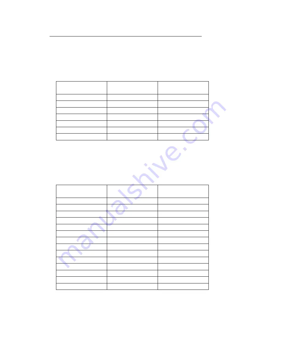
Up to sixteen (16) Uniaxial MEMS sensors are connected to the Canary 6 wire
Multiplexer through the weather tight strain relief fittings mounted to the Datalogger
enclosure; with the final connection made to the terminal blocks mounted on the
Multiplexer. Each terminal block, or Multiplexer channel, consists of seven (7) clamp
connections. A sample Uniaxial MEMS connection is as follows for terminal block #1
Terminal Block
Location
Sensor Wire Color
Description
1H1
White
MEMS
1L1
White’s Black
MEMS Output -
1H2
Green
Thermistor
1L2
Green’s Black
Thermistor Output-
1H3
Red
+12V Power
1L3
Red’s Black
Power Ground
Shield
Bare
Cable Shield
Up to eight (8) Biaxial MEMS sensors are connected to each Canary 6 wire Multiplexer
through the weather tight strain relief fittings mounted to the Datalogger enclosure; with
the final connection made to the terminal blocks mounted on the Multiplexer. Each
terminal block, or Multiplexer channel, consists of seven (7) clamp connections. A
sample biaxial MEMS connection is as follows for terminal blocks #1 and #2:
Terminal Block
Location
Sensor Wire Color
Description
1H1
White
A axis
1L1
White’s Black
A axis Output -
1H2
Blue
Thermistor
1L2
Blue’s Black
Thermistor Output-
1H3
Red *
+12V Power
1L3
Red’s Black *
Power Ground
Shield
Bare
Cable Shield
2H1
Green
B axis
2L1
Green’s Black
B axis Output -
2H2
No Connection
--
2L2
No Connection
--
2H3
Red *
+12V Power
2L3
Red’s Black *
Power Ground
Shield
Bare
Cable Shield
Note:
* Jumpers required for Sensor Power and Sensor Ground