Geokon 4650 Instruction Manual Download Page 13


3.2 GK-405 Readout Box 


The GK-405 Vibrating Wire Readout is made up of two components: The Readout Unit, 

consisting of a Windows Mobile handheld PC running the GK-405 Vibrating Wire Readout 

Application; and the GK-405 Remote Module, which is housed in a weatherproof enclosure and 

connects via a cable to the vibrating wire gauge to be measured. The two components 

communicate wirelessly using Bluetooth

®

, a reliable digital communications protocol. The 

Readout Unit can operate from the cradle of the Remote Module, or, if more convenient, can be 

removed and operated up to 20 meters (65 feet) from the Remote Module.  


3.2.1 Connecting Sensors with 10-pin Bulkhead Connectors Attached


Align the grooves on the sensor connector (male), with the appropriate connector on the 

readout (female connector labeled senor or load cell). Push the connector into place, and 

then twist the outer ring of the male connector until it locks into place.  


3.2.2 Sensors with Bare Leads 


Attach the GK-403-2 flying leads to the bare leads of a Geokon vibrating wire sensor by 

connecting each of the clips on the leads to the matching colors of the sensor conductors, 

with blue representing the shield (bare). 


3.2.3 Operating the GK-405 


Press the button labeled “POWER ON (BLUETOOTH)”. A blue light will begin 

blinking, signifying that the Remote Module is waiting to connect to the handheld unit. 

Launch the GK-405 VWRA program by tapping on “Start” from the handheld PC’s main 

window, then “Programs” then the GK-405 VWRA icon. After a few seconds, the blue 

light on the Remote Module should stop flashing and remain lit. The Live Readings 

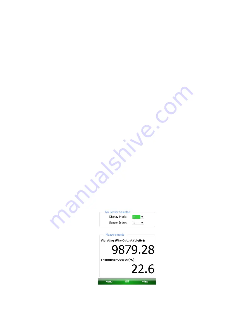
Window will be displayed on the handheld PC. Choose display mode “B”. Figure 5 

shows a typical vibrating wire output in digits and thermistor output in degrees Celsius. If 

no reading displays or the reading is unstable, see Section 11 for troubleshooting 

suggestions. For further information, consult the GK-405 Instruction Manual. 


Figure 5 - Live Readings – Raw Readings 


Summary of Contents for 4650

Page 1: ...means without the written consent of Geokon The information contained herein is believed to be accurate and reliable However Geokon assumes no responsibility for errors omissions or misinterpretation The information herein is subject to change without notification Copyright 1984 2018 by Geokon Doc Rev S 12 19 18 ...

Page 2: ......

Page 3: ...nnel There are no warranties except as stated herein There are no other warranties expressed or implied including but not limited to the implied warranties of merchantability and of fitness for a particular purpose Geokon is not responsible for any damages or losses caused to other equipment whether direct indirect incidental special or consequential which the purchaser may experience as a result ...

Page 4: ......

Page 5: ...ULATION OF SENSOR ELEVATION 9 4 2 CORRECTION FOR SETTLEMENT OR HEAVE OF THE RESERVOIR TERMINAL 10 4 3 CORRECTIONS FOR TEMPERATURE 10 5 SPECIAL TOOLS AND APPARATUS REQUIRED FOR VARIOUS TEST PROCEDURES 12 6 FLUSHING PROCEDURES 12 7 PURGING THE VENT LINES 13 8 IN SITU CALIBRATION 14 9 IN SITU ZERO CHECK 15 10 MAINTENANCE 15 11 TROUBLE SHOOTING 16 11 1 UNSTABLE READINGS 16 11 2 READING OF 9999 16 11 3...

Page 6: ...gure 8 In Situ Calibration Apparatus 14 Figure 9 Tube Insertion 21 Figure 10 Make a Mark at Six O clock 21 Figure 11 Tighten One and One Quarter Turns 21 Figure 12 Marks for Reassembly 22 Figure 13 Ferrules Seated Against Fitting Body 22 Figure 14 Tighten Nut Slightly 22 TABLES Table 1 Specifications 17 Table 2 Thermistor Resistance versus Temperature 18 EQUATIONS Equation 1 Elevation 9 Equation 2...

Page 7: ...asure the settlement inside an embankment The sensor is read by means of an electrical cable extending to the readout location Readings may be taken using a readout box or datalogger Figure 1 Typical Installation of Vibration Wire Settlement System The sensor Figure 2 contains a thermistor for measurement of temperature as well as gas discharge tubes for protection against lightning damage The cab...

Page 8: ... use of two liquid filled tubes permits the tubing to be flushed periodically to remove any accumulation of air bubbles With this type of liquid settlement sensor it is vital that there be no air bubbles in the liquid line The liquid used is typically a de aired antifreeze mixture which resists the growth of algae and is not susceptible to freezing Figure 3 Reservoir Details ...

Page 9: ...ize removed This material should be tamped down around the cell until the excavation is filled back to the original ground surface The elevation of the settlement plate should be measured at the time of the installation using conventional level survey techniques Check also that the sensor is still functioning after tamping 2 2 Installing the Cables and Liquid Filled Tubes Cables and tubing need to...

Page 10: ...p and the breather tube are removed from the ends of the sensor tubing air is not sucked into the tubing by a built up negative pressure When connecting the tubes from the sensor to the reservoir do not allow air to be trapped inside the tubing Installation is as follows 1 With the reservoir valve closed remove one of the caps from the fitting at the base of the reservoir as well as the cap that d...

Page 11: ... a constant temperature If the tubes are not completely buried the readings should be taken at a time when the temperature is relatively constant The readings should never be taken when the tubes are exposed to direct sunlight In addition there should be no air bubbles in the liquid tubes If air bubbles are detected the tubes should be flushed before the initial readings are taken If there is any ...

Page 12: ...onnector to GK 404 Connect each of the clips on the leads to the matching colors of the sensor conductors with blue representing the shield bare To turn the GK 404 on press the ON OFF button on the front panel of the unit The initial startup screen will be displayed After approximately one second the GK 404 will start taking readings and display them based on the settings of the POS and MODE butto...

Page 13: ... of the male connector until it locks into place 3 2 2 Sensors with Bare Leads Attach the GK 403 2 flying leads to the bare leads of a Geokon vibrating wire sensor by connecting each of the clips on the leads to the matching colors of the sensor conductors with blue representing the shield bare 3 2 3 Operating the GK 405 Press the button labeled POWER ON BLUETOOTH A blue light will begin blinking ...

Page 14: ... change one or two digits while reading 4 The thermistor reading will be displayed above the gauge reading in degrees centigrade 5 Press the Store button to record the value displayed If the no reading displays or the reading is unstable see Section 11 for troubleshooting suggestions The unit will automatically turn off after approximately two minutes to conserve power 3 4 Measuring Temperatures A...

Page 15: ... E0 is the sensor elevation at installation ERES is any change of the fluid level inside the reservoir sight glass If the fluid level falls ERES is negative If the fluid level rises ERES is positive R0 is the initial sensor reading R1 is the subsequent sensor reading G is the calibration factor supplied with the sensor A typical calibration report supplied by the factory is shown in Figure 6 For E...

Page 16: ...cautions may be necessary to obtain readings at times of maximum temperature stability Temperature effects on the sensor can be corrected for but are usually quite insignificant especially if the sensor is buried The elevation ET corrected for temperature is given by ET E0 R1 R0 G T1 T0 K ERES Equation 2 Elevation corrected for temperature Where T0 is the initial temperature T1 is the current temp...

Page 17: ...11 Figure 6 Typical Calibration Report ...

Page 18: ...d with de aired liquid Dye added to the new flushing fluid can be used to indicate when the flushing is complete The best way to de air a liquid is to use a Nold DeAerator ask Geokon for more details De aired liquid is also available from Geokon in two gallon or five gallon pressure tanks specially designed to prevent air from reaching the fluid The liquid should also resist the growth of algae an...

Page 19: ...8 Store the flushed liquid in a container for later disposal Do not allow any liquid to enter the vacuum pump as this could ruin it 9 When flushing is complete reconnect the fluid lines to the base of the reservoir Be careful not to introduce air bubbles during this process 7 PURGING THE VENT LINES The vent line must remain open at all times it connects the inside of the sensor to the space above ...

Page 20: ...iliary reservoir by measured amounts using a scale to measure the elevation of the water level Read the sensor using a GK 403 GK 404 or GK 405 readout box See Section 3 for readout instructions Record the readings after allowing sufficient time for the readings to stabilize usually requires around one to five minutes although it will be noted that the sensor responds instantaneously to change of w...

Page 21: ...d lines following the flushing procedures described in Section 6 with the following difference If a vacuum pump is used allow the vacuum pump to run for 30 minutes or until the sensor reading has stabilized before opening the valve at the bottom of the filling tank to allow liquid to enter the lines This will greatly reduce the chances of air being trapped inside the tubing and sensor cavities 10 ...

Page 22: ...ction 6 and Section 7 11 2 Reading of 9999 These will show up on dataloggers if the reading is overrange This can happen if the electrical leads are shorted or open Check the resistance between the black and red conductors The resistance should be 180 ohms 10 ohms plus five ohms for every 100 meters 328 feet of lead wire If the resistance is substantially different from these values check for loos...

Page 23: ...tegral 3 175 mm 1 8 diameter polyethylene vent tube Resistance 5 25 ohm 100 m 14 7 ohms 1000 ft Liquid tubes Twin type 11 nylon tubes 6 35 mm 1 4 O D covered with one millimeter polyethylene jacket Liquid A de aired 55 45 solution of distilled water mixed with commercial grade propylene glycol Specific gravity 1 041 Freezing point is 30 C 22 F Desiccant Capsules Geokon Model 4500 8 Table 1 Specifi...

Page 24: ...2 83 107 9 123 77 66K 36 8006 4 1363 44 331 5 84 105 2 124 72 81K 35 7618 5 1310 45 321 2 85 102 5 125 68 30K 34 7252 6 1260 46 311 3 86 99 9 126 64 09K 33 6905 7 1212 47 301 7 87 97 3 127 60 17K 32 6576 8 1167 48 292 4 88 94 9 128 56 51K 31 6265 9 1123 49 283 5 89 92 5 129 53 10K 30 5971 10 1081 50 274 9 90 90 2 130 49 91K 29 5692 11 1040 51 266 6 91 87 9 131 46 94K 28 5427 12 1002 52 258 6 92 85...

Page 25: ...vel is maintained during the splicing operation and that the balance tube is disconnected from the top of the reservoir 1 Cut one of the tubes about 50 mm 2 beyond the yellow jacket and immediately block the end so that no fluid can flow 2 Place the correct nut and ferrule pack over the end of this tube and then block the flow 3 Next remove the cap from one of the lines on the replacement sensor a...

Page 26: ...erly 7 Place the cable in its epoxy splice kit and make the splice 8 Do the same for the tubing assembly C 2 Adding an Extension to a Sensor Assembly The first step in this operation is to connect the supplied section of tubing to the reservoir This should be done with the liquid flowing from the reservoir in the same way that the operation is done when connecting a sensor After connecting the ext...

Page 27: ...high safety factor systems further tighten the nut until the tube will not turn by hand or move axially in the fitting 3 Mark the nut at the six o clock position Figure 10 Make a Mark at Six O clock 4 While holding the fitting body steady tighten the nut one and one quarter turns until the mark is at the nine o clock position Note For 1 16 1 8 3 16 and 2 3 and 4 mm fittings tighten the nut three q...

Page 28: ... Inspect the ferrules for damage and replace if necessary If the ferrules are replaced the connector should be treated as a new assembly Refer to the section above for installation instructions 4 Reassemble the fitting by inserting the tube with preswaged ferrules into the fitting until the front ferrule seats against the fitting body Figure 13 Ferrules Seated Against Fitting Body 5 While holding ...

Reviews: