


2
2. GAGE INSTALLATION -GENERAL
2.1 Preliminary Tests
A preliminary check is advisable, and this is made by placing the coil assembly onto the
gage and connecting it to the GK-401, GK-402 or GK-403 Readout Box. Switch the position
selector to "C" and turn the unit on. While gently pulling on the gage end blocks, observe
the reading; it should be seen to increase with increased tension. Do not apply excessive
tension, (>10Kgm (20lbs)), as the wire could break. The nominal reading range is 1000 to
4000 microstrain. Mid-range is approximately 2500 microstrain.
Check the resistance between the two lead wires (red and black). It should be around 180
ohms. If the gage contains a thermistor, check its resistance between the white and green
lead wires. (The resistance should be around 3000 ohms at 25 degrees C). Check the
reading against that which should be obtained at the existing ambient temperature. See
Appendix C
for the resistance versus temperature correlation.
Return any faulty gages to the factory. Gages should not be opened in the field.
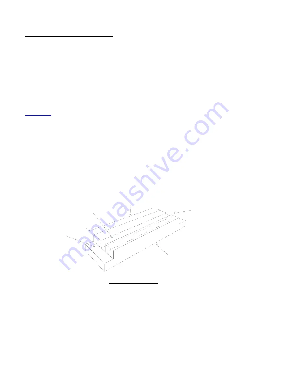
2.2 Arc Welding the Mounting Blocks to Steel Surfaces – Using the Spacer Bar
The Model 4000 Vibrating Wire Strain Gage is attached to mounting blocks that must first be
arc welded to the steel surface to be studied. A spacer bar and spacing jig are used to
correctly space apart the two blocks. Figure 2 shows the procedure: the two mounting
blocks are fitted over the ends of the spacer bar, and the jig is used to position them
correctly, while the set screws in the mounting blocks are tightened down onto the spacer
bar. Avoid excessive tightening as this only damages the spacer bar unduly.
The mounting blocks are supplied in pairs; one has a single cone point set-screw, the other
has two cone point set-screws.
Aluminum Block
Mounting Block
Spacer Bar (in slot)
Mounting Block
Position
Position
Setting Distance
Figure 2 - Spacing Jig


