EB-GS2985-S
Evaluation Board User Guide
52246 - 2
July 2009
6 of 25
1.1 SDI Inputs and Outputs
EB-GS2985-S features a single ended 75
Ω
input through a BNC connector (SDI) and two
single ended 75
Ω
outputs through two BNC connectors (SDO, SDO).
1.2 DDO1/RCO Output
The EB-GS2985-S features two SMA connectors (DDO1/RCO, DDO1/RCO) for the
recovered clock RCO and RCO or the data DDO1 and DDO1. This can be selected using
the position on SW1 marked DATA/CLOCK.
1.3 SPI Interface
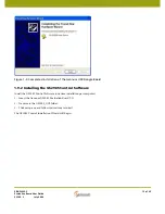
The EB-GS2985-S features an SPI interface (JP1) which is used to access all of the GS2985
registers. The SPI interface is automatically enabled when the Gennum USB dongle is
connected. The Gennum USB Dongle can connect the EB-GS2985-S to a computer via
USB. When the ribbon cable on JP1 is removed, the SPI interface is automatically
disabled and the board goes into legacy mode. The GS2985 registers will maintain their
settings until the board is powered-down, or reset via the SPI interface.
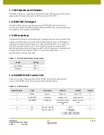
Table 1-1
describes the two modes of operation.
1.4 GS2985 RCLK Control I/O
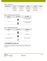
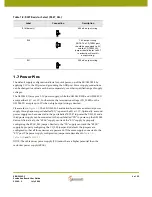
There are a variety of components on the EB-GS2985-S board to facilitate manual
control of the GS2985 device. These are described in the tables below.
Table 1-1: SPI Interface Modes of Operation
Mode
Setting
Legacy Mode
HIF = 1
SPI Mode
HIF = 0
Table 1-2: SW1 Positions
Switch Position
Label
Description
HIGH (1)
LOW (0)
Default
1
BYPASS
Bypass
Bypass On
Bypass Off
0
2
AUTOBYPASS
Autobypass
Autobypass On
Autobypass Off
1
3
AUTO/MAN
Auto/Manual
Automatically locks
to incoming data
rate
Manual data rate
select
1
4
SS0
Data rate select [0]
SS[1:0]
0 - Reserved
1 - 270 (Mb/s)
2 - 1485 or 1485/1.001 (Mb/s)
3 - 2970 or 2970/1.001 (Mb/s)
0
5
SS1
Data rate select [1]
0


