background image

7

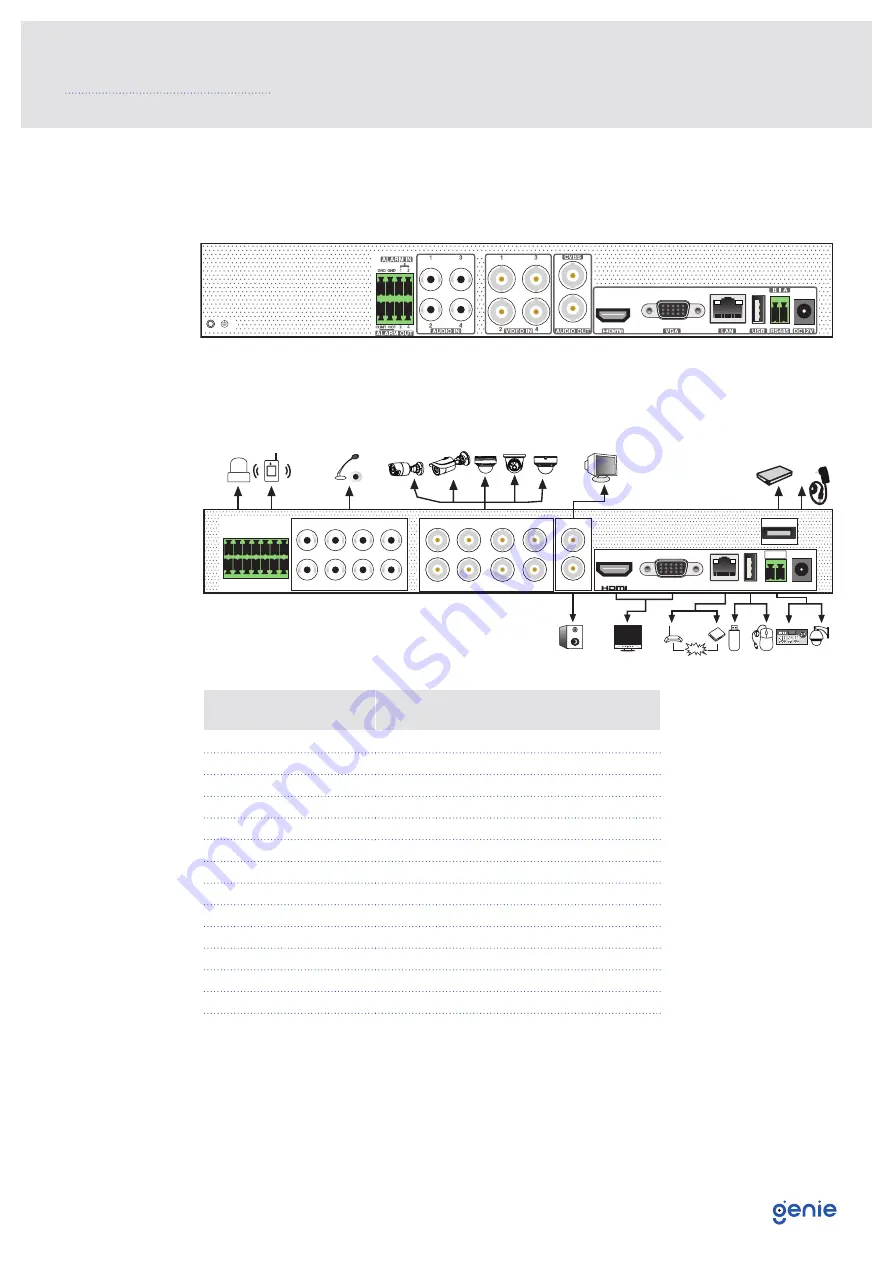
The interfaces of the rear panel are for reference only.

Rear panel for WAHD241A

Rear Panel for WAHD281A

3.0 Rear Panel Instruction

Internet

CVBS

DC12V

USB

e SATA

LAN

VGA

B           

AUDIO IN

1

5

2

6

3

7

4

8

VIDEO IN

1

2

5

6

8

7

3

4

AUDIO OUT

RS485

GND

GND

8

4

COM2

COM1

NO2

NO1

7

6

2

5

3

1

ALARM OUT ALARM IN

A

Name

Description

ALARM OUT

Relay output, connect to external alarm

ALARM IN

Alarm input for connecting sensors

GND

Ground

AUDIO IN

Audio input

VIDEO IN

Video input

CVBS

CVBS output

AUDIO OUT

Audio output

HDMI

Connect to high definition display device

VGA

Connect to monitor

LAN

Ethernet connector

USB

Connector for USB devices

e-SATA

Connector for e-SATA

RS485

Connector for RS485 devices. A is TX+,B is TX

DC12V

Power input

Summary of Contents for WAHDN281A

Page 1: ...Quick Start Guide Please read these instructions carefully before operating the unit and keep for further reference 8 Channel 5 in 1 High Definition 1080p DVR with 1HDD Bay and Alarms WAHDN281A...

Page 2: ...urther reference All examples and pictures used here are for reference only The contents of this manual are subject to change without notice CAUTION Please check the device and the accessories after g...

Page 3: ...D Installation 6 3 0 Rear Panel Instruction 7 4 0 Start Up and Shut Down 8 5 0 Login 9 6 0 Configurations and Connections 10 6 1 Ananlogue Camera Connection 10 6 2 Network Configuration Adding IP Came...

Page 4: ...ics User Interface GUI Window style operation by mouse Multi mode recording Manual Timer Motion Playback 8 CH simultaneous playback Multi user online simultaneously Search Time Slice Time Event Manual...

Page 5: ...anual Timer Motion Smart Event Mobile Device OS iOS Android Storage HDD SATA x1 up to 8TB E SATA x1 Playback Playback 8CH Search Time Slice Time Event Tag Search Smart Search Highlight colours to disp...

Page 6: ...into the HDD but do not tighten them 3 Place the HDD onto the bottom of the machine 4 Turn over the machine and secure the HDD with the screws 5 Connect the power and data cables 6 Install back the c...

Page 7: ...NO2 NO1 7 6 2 5 3 1 ALARM OUT ALARM IN A Name Description ALARM OUT Relay output connect to external alarm ALARM IN Alarm input for connecting sensors GND Ground AUDIO IN Audio input VIDEO IN Video in...

Page 8: ...oot and the power indicator will display blue 3 A wizard window will pop up Shutdown Click Start and then select Shutdown icon This will bring up a shutdown window The device will shut down by clickin...

Page 9: ...the DVR for the first time and you may change the password when you configure the wizard for the first time You can skip the settings wizard next time Click Start and select Login This will take you...

Page 10: ...s via LAN WAN LAN 1 Set the network of the DVR Go to Start Settings Network TCP IP Enter IP address subnet mask gateway etc If using DHCP please enable DHCP in both the DVR and the router 2 Go to Star...

Page 11: ...dded device and click button to modify channel IP address etc WAN 1 Set the network of the DVR Go to Start Settings Network PPPoE Enter static IP address or enable PPPoE and then enter the user name a...

Page 12: ...UPnP and then click Apply button to save 2 Enable the UPnP function in the router 3 Click Refresh button to refresh the UPnP status If the UPnP status were still Invalid UPnP after refreshing it for...

Page 13: ...m Click Apply to save the parameters NAT Access After finishing the NAT settings you can enter www autonat com in the address bar of your browser and then press enter to go to the following interface...

Page 14: ...to select or drag the playback progress bar to change the playback time to play back the record General Playback Click on the tool bar at the bottom of the live preview interface or click Start Playba...

Page 15: ...Sales 44 0 1707 330541 Enquiries sales genieproducts co uk Website www genieproducts co uk...

Reviews: