


Section 4 • Repair Procedures
November 2014
Part No. 229753
GS-2669 RT • GS-3369 RT • GS-4069 RT
4 - 9
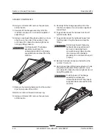
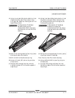
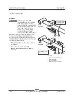
20 Remove the two carriage bolts that secure the
inner arm and chassis pivot to the steer end of
the drive chassis.
21 Move the linkage towards the non-steer end of
the machine until the slider feet are clear of the
slider channel.
22 Carefully lift the linkage assembly off of the
machine and place it on a structure capable of
supporting it.
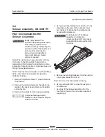
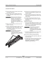
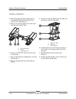
Separate the link sets:
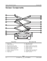
1 Using an overhead lifting device attach a 4 hook
sling chain to the ends of the inner arm (index
#8, #11 or #14). Make the chains tight but do
not apply lifting pressure.
Crushing hazard. The linkage
assembly could become
unbalanced and fall if not properly
supported when removed from the
machine.
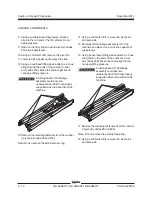
2 Remove the retaining fasteners from the center
pivot pins (index #5, #7 or #12).
Note: Do not remove the external snap ring.
3 Using a soft metal drift, remove the center pivot
pins and set aside.
4 Carefully lift and separate the linkage assembly
apart and place it on a structure capable of
supporting it.
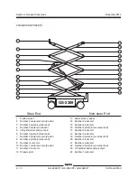
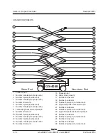
SCISSOR COMPONENTS
Summary of Contents for GS-2669 RT
Page 169: ...Section 6 Schematics November2014 6 9 Control Panel Circuit Diagram 6 10 ...
Page 235: ...Section 6 Schematics November2014 6 75 6 76 Electrical Schematic GS 4069 RT Gas LPG Models AS ...
Page 238: ...November2014 Section 6 Schematics 6 78 Electrical Schematic GS 4069 RT Gas LPG Models AS 6 77 ...
Page 243: ...Section 6 Schematics November2014 6 83 Electrical Schematic GS 4069 RT Diesel Models AS 6 82 ...
Page 246: ...November2014 Section 6 Schematics 6 86 Electrical Schematic GS 4069 RT Diesel Models AS 6 85 ...
Page 251: ...Section 6 Schematics November2014 6 91 Electrical Schematic GS 4069 RT Gas LPG Models CE 6 92 ...
Page 254: ...November2014 Section 6 Schematics 6 94 Electrical Schematic GS 4069 RT Gas LPG Models CE 6 93 ...
Page 259: ...Section 6 Schematics November2014 6 99 6 100 Electrical Schematic GS 4069 RT Diesel Models CE ...
Page 267: ...Section 6 Schematics November2014 6 107 Hydraulic Schematic GS 2669 RT and GS 3369 RT 6 108 ...
Page 270: ...November2014 Section 6 Schematics 6 110 Hydraulic Schematic GS 4069 RT 6 109 ...


