background image


- 22 -

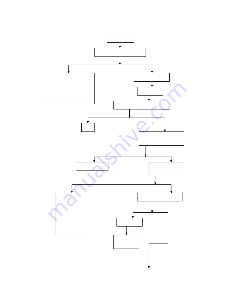
Diagnosis on engine overheating   


Engine overheating

Check whether operation is correct 

1.


Check whether gasoline grade is 
improper or stored for a long 
time 

2.


Check whether the engine works 
at high speed for a long time or 
with overload during driving 

Check cooling system   

Air-cooled engine   

Check whether heat sink is spotted or there
is too much oil stain


Clean  

Check whether cooling fan or air 
director is damaged (forcedly 
air-cooled engine) 

Inspection & solution   

Check whether ignition is
timely conducted with an
ignition timing light 

1.


Check whether 
CDI ignition 
device is in good 
condition 

2.


Check whether 
flywheels and 
trigger coil are 
loosened 

Check whether clutch is slipping   

Slipping clutch 

Solution to 

slipping clutch   

Summary of Contents for Onyx 50

Page 1: ...Service Manual Holtvej 8 10 Høruphav 6470 Sydals Telefon 45 73 15 11 00 Fax 45 73 15 11 01 info scanmi dk www scanmi dk CVR 27 73 31 07 www genericmotor dk Juli 2011 ONYX 50 ...

Page 2: ...ONYX Service Manual Generic Motor GmbH ...

Page 3: ...rging system 55 1 1 Preparing documents 55 1 2 Failure diagnosis 56 1 3 Battery 57 1 4 Charging system 58 1 5 Rectifier 59 1 6 Magnetor charging coil 60 1 7 Replacement of magnetor 61 2 Ignition system 64 2 1 Preparing documents 64 2 2 Failure diagnosis 65 2 3 Checking the ignition system 66 2 4 CDI Group 68 2 5 Ignition coil 69 2 6 Trigger 70 ...

Page 4: ...iagnosis 79 4 3 Headlight bulb replacement 79 4 4 Front turn signal lamp bulb replacement 80 4 5 Taillight Rear turn signal lamp replacement 80 4 6 Meters 81 4 7 Main switches 81 4 8 Speakers 81 4 9 Combined switch 82 Examination and maintenance of chassis 83 5 Brake 86 5 1 Maintenance instruction 86 5 2 Failure Diagnosis 87 5 3 Front fluid brake 87 5 4 Rear drum brake 89 6 Body panel 93 ...

Page 5: ...cuments 106 8 2 Failure diagnosis 106 8 3 Rear wheel 107 8 4 Rear shock absorber 108 9 Fuel tank seat 114 9 1 Preparation documents 114 9 2 Failure diagnosis 114 9 3 Fuel tank seat 115 10 Removal installation of motor 117 10 1 Preparation documents 117 10 2 Failure diagnosis 117 10 3 Removal of motor 118 10 4 Installation of motor 119 Inspection and maintenance of motor 120 11 Lubricaiton system 1...

Page 6: ...ent 130 13 Cylinder cap 133 13 1 Preparation documents 133 13 2 Failure diagnosis 133 13 3 Cylinder cap 133 13 4 Cylinder cap inspection 134 13 5 Installation of cylinder cap 134 14 Cylinder body and piston 137 14 1 Preparation documents 137 14 2 Failure diagnosis 138 14 3 Cylinder body 138 14 4 Piston 139 14 5 Installation of piston 142 15 Driving clutch driven wheel foot driving device 146 15 1 ...

Page 7: ... Gear box 158 16 4 Installation 159 17 Crankcase 161 17 1 Preparation documents 161 17 2 Failure diagnosis 161 17 3 Crankcase 162 17 4 Installation 164 Inspection and maintenance of exhaust gas discharge control system 164 18 Exhaust gas discharge control system 166 18 1 Exhaust gas discharge control system reconizance 166 18 2 Regular maintenance notes 166 18 3 Mechanic function of exhaust gas di...

Page 8: ... 6 18 5 Solution for idle discharge value exceeding defined value two stroke 169 ...

Page 9: ...ried out from the beginning of periodic inspection Except for chapter one the rest chapters explain the disassembly assembly inspection of engine entire motorcycle and electrical parts Breakdown drawing systematic drawing failure analysis and statement are contained at the first part of each chapter Please note that photos pictures or instructions are for your reference only The actual object may ...

Page 10: ...ace not in a closed area Note Exhaust gas contains poisonous carbon monoxide which may cause unconsciousness or even death of human being Start engine in an open place The exhaust cleaning system shall be adopted if engine is started in a closed area Petrol Ventilated place is required for working Fire is strictly forbidden in work place or where petroleum is stored ...

Page 11: ...chine after disassembly and before measurement of attrition value Solvent or oil can easily damage aging rubber articles Check rubber before reassembly and replace rubber if necessary When releasing assembly parts please start from outside to inside Small assembly parts shall be loosened first Complex assembly parts such as gear box shall be stored in proper order for facilitating installation in ...

Page 12: ...installing a hosepipe fuel vacuum or cooling agent insert its end into the bottom of the connector so that the hose clip can properly fix the connector Rubber or plastic dirt proof boot shall be mounted according to the original design During dismantling ball bearing one or two inside outside bearing rollers shall be supported by tools Ball bearings may be damaged and have to be replaced if only o...

Page 13: ...s may be clamped during moving Cables along the handlebar shall be neither too tight nor too loose and do not interface with any neighboring parts at steering positions Cables shall be properly deployed without twist or knot Check whether the connector jacket is damaged and whether the connector is over stretched before mounting connectors Adopt adhesive tape or hosepipe to protect cables if they ...

Page 14: ... 2 Only metric tools are valid for maintenance and repair Metric screws bolts and nuts can not be exchanged with imperial fasteners 3 New gaskets O rings cotter pins and locking pieces shall be applied for re assembly 4 Bolts with large diameter or positioned inside shall be fastened first and then diagonally screw down until reaching required torque otherwise there is special instruction 5 Wash d...

Page 15: ...1 1 1 2 of special tools for disassembling assembling engine parts are as follows Table 1 1 Name Remark Special socket spanner Clutch clamp holder Flywheel puller Feeler gauge Bearing disassembly tools Bearing assembly tools Oil seal remover Handle for dismantling tools Piston pin pulling device Piston pin pliers Socket spanner for spark plug Clutch thickness measuring device Cylinder diameter mea...

Page 16: ... 14 Fig 1 5 Fig 1 6 Fig 1 7 Fig 1 8 Fig 1 9 Fig 1 10 handle Fig 1 11 Fig 1 12 Thickness gauge feeler gauge ...

Page 17: ...orque spanner Inner hexagon spanner Socket spanner Dial indicator Magnetic rack V block Micrometer Vernier calipers Circlip pliers Screwdriver with striking cap Tool for assembling oil seal of front fork Tool for hammering seal of front fork Steering nut spanner Fig 1 19 Fig 1 20 Fig 1 21 Fig 1 22 Fig 1 23 Fig 1 24 Fig 1 25 Fig 1 26 Fig 1 27 Fig 1 28 Fig 1 29 Fig 1 30 1 Ordinary tools for repairin...

Page 18: ... 1 20 Fig 1 21 Fig 1 22 Fig 1 23 Fig 1 24 Fig 1 25 Fig 1 26 Fig 1 27 Fig 1 28 2 Special tools for repairing chassis tool for hammering seal of front fork 1 socket head 2 crank handle 3 ratchet spanner 4 connecting rod ...

Page 19: ...ner Fig 1 30 3 Tools for electric parts List and drawings 1 31 1 32 of special tools for testing electric parts are as follows Table 1 31 Name Remark Multimeter Ignition tester Fig 1 33 Fig 1 34 Table 1 32 continued Fig 1 33 Fig 1 34 ...

Page 20: ... rim 16X1 6 Rear outer tyre 90 80 16 Air filter AF B45 Tyre Size Rear rim 16X1 85 Capacity of gasoline tank 5 5 L 0 2L Clutch Dry centrifugal clutch Variable speed gear Stepless Engine Carburetor type PZ19JB 2K Transmission gear Transmission Belt transmission Idle speed 1900 100rpm min Max torque 4 36N m 5250rpm Battery capacity 12V 4AH Max Hp 2 60kW 6500rpm Electromagnetic motor capacity 90W 5000...

Page 21: ... 19 system I D of brake drum rear wheel φ140mm QJ50QT 22D ...

Page 22: ...ion Check power supply for ignition Check whether short circuit or open circuit occurs to ignition coil Check whether short circuit or open circuit occurs inside the ignition system Check whether CDI ignition device is in good condition Check the compression pressure of cylinder with pressure gauge Check whether there is gasoline in the fuel tank Normal compression pressure Insufficient compressio...

Page 23: ...irmly closed 2 Check whether the conical surface of float needle valve is abrasive as steps 3 Check whether the float needle valve is broken 4 Check whether the float needle valve is too low Check whether air filter is blocked Flameout shortly after startup Continue to work after startup The carburetor is blocked inside or the float is too high Startup device of carburetor startup enrichment syste...

Page 24: ... Check cooling system Air cooled engine Check whether heat sink is spotted or there is too much oil stain Clean Check whether cooling fan or air director is damaged forcedly air cooled engine Inspection solution Check whether ignition is timely conducted with an ignition timing light 1 Check whether CDI ignition device is in good condition 2 Check whether flywheels and trigger coil are loosened Ch...

Page 25: ...ng acceleration the carburetor generates backfire insufficient power of engine Mixed combustible gas is too dense 1 Check whether the air filter is blocked 2 Check whether the startup device for carburetor startup enrichment system works normally 3 Check whether the float needle valve is too low Normal combustible gas mixture Check whether the cylinder outlet or the exhaust muffler is blocked due ...

Page 26: ...ptured blocked in the groove or lacks elasticity 6 Check the abrasion of piston ring and cylinder Start the engine and slow accelerate observe the rotation speed change of engine The rotation speed of engine rises as it slowly accelerates The rotation speed of engine does not rise as it slowly accelerates Check whether ignition is timely conducted with an ignition timing light 1 Check whether the ...

Page 27: ...k whether idle jet is too big Check whether the steel wire rope of accelerator control cable is flexible when pulling and whether the throttle valve spring is too soft Check whether the electrode clearing of spark plug is toosmall 1 Check whether CDI ignition device is in good condition 2 Check whether flywheels and trigger coil are loosened Idle speed after adjustment No idle speed after adjustme...

Page 28: ...Low pressure Normal pressure Inflate as required Check whether oil leakage occurs in fuel box fuel cock oil pipe and carburetor Solve problems based on actual situation Check the proportion of mixed combustible gas Normal combustible gas mixture Mixed combustible gas is too dense Mixed combustible gas is diluted Check whether the idle speed of engine is too high 1 Check whether the air filter is b...

Page 29: ...ptured or lacks elasticity Replacement Disassemble crankcase and check whether the depth in engaging for each gear is in accordance with requirements Proper depth in engaging Insufficient depth in engaging Check whether the engaging end of the cam claw on the engaged gear face is abraded to be conical or largely circular and whether the groove on the corresponding gear face is abraded to be trumpe...

Page 30: ...ged 4 Check whether the piston surface of brake caliper and the wall of oil tank are excessively abraded or damaged Malfunction of drum brake Check whether the free stroke of brake lever is within 10mm 20mm or whether the free stroke of brake pedal is within 20mm 30mm Readjustment Separate the brake arm and the steel wire rope of brake control cable check the brake arm with hands The brake arm wor...

Page 31: ...ter connection The starter motor works normally after short circuit The starter motor does not work after connection and there is no sound from starting relay The starter motor does not work after short circuit Open circuit or short circuit of starting relay coil Check the inner circuit of the electric starting control system Contacts of starting relay are burnt or damaged Disassemble the starter ...

Page 32: ...tarter motor is bad Disassemble the lead wires connecting to starter motor and battery from the starting relay and press the starting button Check whether the resistance between the battery terminal and the starter motor terminal is normal with ohm meter when the starting relay makes connection sound Inspection elimination Disassemble the starter motor and check 1 whether the carbon brush is exces...

Page 33: ...The horn can make loud sound and the steering lamp is light The horn can not make loud sound and the steering lamp is not light Normal battery power supply Rapidly strike a lead wire on the negative positive poles of battery and check spark No spark Spark Power shortage of battery 1 Check whether the fuse is burnt out 2 Check whether open circuit or short circuit occurs between the battery and ign...

Page 34: ...ctrolyte density inside the battery is too low 4 Check whether the battery plate is sulfurized or short cut Remove the connector between the rectifier regulator and the cable assembly check whether there is open circuit between the lighting charging coil of electromagnetic motor and the rectifier regulator with an ohm meter Set the multimeter to DC voltage 0V 20V measure the voltage between the co...

Page 35: ...ness of lamps The lamp works normally Still weak light from the lamp Low stable voltage of rectifier regulator Check whether there is short circuit in the charging coil of electromagnetic coil and the charging system The horn makes loud sound and the steering lamp emits bright light The horn makes coarse sound the steering lamp emits weak light Power shortage of battery or bad connection between b...

Page 36: ...orn button and check whether the horn works normally The horn makes loud sound The horn can not make or makes coarse sound Normal battery power supply Battery power supply shortage Remove the steering lamp cover and check whether the bulb is burnt Turn the steering lamp switch and use a lead wire or a screwdriver to short circuit two lugs of flasher Replace steering lamp bulb and check whether the...

Page 37: ...wer line terminal of the electric horn and strike the power cord with the earth check the spark Spark available No spark Connect to the power cord of electric horn use a screwdriver to contact the non power cord terminal to button with the earth Short circuit between the ignition switch and electric horn The electric horn makes sound The electric horn does not make sound Bad contact inside the hor...

Page 38: ... switch or brake lamp switch Power shortage of battery Check whether the brake lamp is always light Adjust or replace the brake lamp switch Leakage current is lower than the required value Leakage current is higher than the required value Normally the leakage current is required to be no more than 1mA Check whether short circuit occurs to the charging coil of electromagnetic motor Short circuit be...

Page 39: ... regulator No voltage Voltage available Open circuit between the connector and the battery Check whether the rectifier or the rectifier regulator is broken down with an ohm meter Remove the connector between the conductor bundle of electromagnetic motor and the cable assembly measure the resistance between the output conductor terminals of charging coil and check whether it is in accordance with t...

Page 40: ... Headlight Battery Clutch Carburetor Front rear suspension system Ignition timing Bolt nut fastener Rim tyre Tyre specification Preparing principles General Warning 1 Make sure that it is well ventilated before starting the engine It is forbidden to start it in a closed area Exhaust gas which contains monoxide may cause unconsciousness or even death of human being The petrol is liable to volatile ...

Page 41: ...62 N m Torque value Fixing nut for rear wheel 100 113 N m Certification for Related Parts Type Name Certificate No Front outer tyre E11 75R 001062 Tyre Rear outer tyre E11 75R 001063 Front lamp E9 00 1555 Position lamp E9 50R 001555 Tail lamp E9 50R 001556 Front steering lamp E9 50R 001557 Rear steering lamp E9 50R 001558 Lamps Rear registration plate lamp E11 50R 000066 Rear view mirror Rear view...

Page 42: ...I I I I I Densimeter multimeter Actuation gap inspection I I I I I I Ordinary tools Inspection of steering handle fastening I I I Ordinary tools Absorber working inspection I I I Ordinary tools Screw fastening inspection I I I I I I Torque spanner Oil leakage inspection for gearbox I I I I I I Ordinary tools Inspection or replacement of spark plug I I R R I Ordinary tools Replacement of gearbox oi...

Page 43: ...blocked Please have your motorcycle inspected and adjusted periodically at Generic distributors for being in best condition The above table is established under the presupposition of 1000 km month I Inspection A Adjustment R Replacement C Cleaning L Lubrication Note 1 Regulations on exhaust emission made by the State Environmental Protection Agency shall be complied with Maintenance must be carrie...

Page 44: ...7 Fixing plate of sump Oil replacement Note It will be easier to change the oil when the engine is warming up Turn off the engine Remove the bolt at the bottom of the crankcase and release oil When the oil leaks completely you can install the bolt and packing washer after they are cleaned Add oil to proper level Check the oil leakage when the engine operates at its idling speed Check the oil capac...

Page 45: ...of air filter Remove the filter element 4 on the filter Check weather the filter element is polluted or damaged And replace it with a new element if necessary Remove the pipe clip Remove the filter Check weather the filter is polluted or damaged And replace it with a new one if necessary Replacement time Replace at an early time if the motorcycle is always running on rainy days Note Make sure the ...

Page 46: ...commended Standard C5HSA NGK Heat Type C6HSA NGK Cold Type C7HSA NGK 2 Reuse of spark plug Clean the electrode of spark plug by scratch brush or special tools Check the distance between the central electrode and lateral electrode of spark plug by steel feeler gauge If necessary carefully bend the lateral electrode to adjust the distance Distance of spark plugs 0 60 0 70mm Installed the spark plug ...

Page 47: ...e otherwise inner component of the motorcycle may be damaged Warning First positive and then negative to prevent short circuit Charging state closed circuit voltage inspection Open the cushion Remove the cover of battery container First remove the negative wire and then remove the positive wire Take out the battery Measure the voltage between battery terminals Full charge 13 1V Under charge 12 3V ...

Page 48: ...andard 10 15 hours Rapid 30 minutes Charging complete closed circuit voltage Above 12 8V Do not disconnect the battery during the adjustment of motorcycle otherwise inner component of the motorcycle may be damaged Carburetor Idle speed adjustment Note Idle adjustment was made in the implementation of the engine warm up state and refer to adjusting bolts Implement after warm up of the engine Connec...

Page 49: ...00rpm min Cylinder pressure Operate when the engine warm up Remove the cushion and body shield Remove the spark plug Install the cylinder pressure gauge At full throttle measure the cylinder pressure by starting the engine The following items shall be check in case of a low pressure Whether the gasket of cylinder cover is damaged whether piston ring is damaged whether the air inlet and piston ring...

Page 50: ... gauge and O shape ring is all right and then carry out the installation Tighten the release bolt Fill the crank case with recommended engine oil Install the oil level gauge start the engine and keep it idle running for 2 3 minutes Stop the engine and check out whether the oil level is at the upper limit of oil level gauge after several minutes The engine shall be kept upright during inspection Gu...

Page 51: ...d check the oil level thought the oil indicator In case the brake fluid level is at or below the arrow in the picture certain brake fluid DOT3 or DOT4 shall be added until it reach upper limit Note The oil pump component shall be paralleled with the ground during the inspection Front light Remove the left and right rearview mirror components Remove the front shield Disconnect the lead of front lig...

Page 52: ...system Front Pull the front brake tight and check the absorber Check whether the absorber has leakage or loose Rear Check the rear absorber when operating Check whether part of the absorber is loose or wear Suspend the rear wheel and check it movingly Check whether the suspension bushing of the engine is loose or not Nuts bolts fixed parts Check whether nuts bolts fixed parts are loose or not If a...

Page 53: ...osening tightening them according to the required torque force value Torque force value Front wheel axle 55 62 N m Rear wheel nut 100 113 N m Steering column bearings and handle fix Swing the handle in order to confirm there is no interference with wire Confirm the handle turn freely when the front wheel turns If the handle is loose or unsmooth you should check the steering column bearings Tyre sp...

Page 54: ... 52 ...

Page 55: ...ng parts in electrical system Position and name of fixing componen Torque of fixing N m Rectifier bolt High tension coil fixing bolt Flywheel Fixing bolt Body Shield Bolt Clutch cover bolt of starting motors Set screw nut of clutch cover of starting motors 5 0 9 0 5 0 9 0 12 95 ...

Page 56: ... 54 Charging System 1 Meters assembly 2 Horn 3 Power locking components 4 Frequency conversion flash apparatus 5 Battery 6Temperature controlled 7 Pressure adjuster 8 Ignition coil ...

Page 57: ...will be shortened 3 If the battery has been place without using for a long time it will be self discharged and its capacity will drop Under this condition it should be charged every 3 months 4 Check the charging system following the sequence listed on the table 5 Don t remove the connector with current flowing through the electrical parts otherwise the voltage will be too high and these parts will...

Page 58: ...mit Charging limit 14 8V 0 4V 5000rpm Tightening torque force value Tool Rectifier bolt 5 0 N m Multiple fixing spanner High tension coil fixing bolt 9 0 N m Flywheel remover Flywheel Fixing bolt 5 0 N m Testing instrument Body Shield Bolt 9 0 N m Multimeter 1 2 Failure diagnosis Power supply dead interrupted electric current Battery overcharge Poor contact of the charging wire Battery wire isn t ...

Page 59: ...dangerous that spark caused by short circuit will spark the petrol and break the battery Do not disconnect the battery during the adjustment of motorcycle otherwise inner component of the motorcycle may be damaged Install the battery in an opposite order Note First positive terminal then negative terminal to prevent short circuit Check the charging situation Open the battery cover and remove the c...

Page 60: ...ng charging Take the marked current time as a standard when charging Note Except emergencies you should not use emergency charge Measure the voltage for every other 30 minutes Charging current standard0 4A emergency 4 0A Charging time standard 10 15h emergency 30min Charging completes open circuit voltage above12 8V 1 4 Charging system 1 4 1 Charging system Remove the batter ground wire and connec...

Page 61: ...art the engine slowly and measure the limiting voltage and current 万用电表 multimeter Limiting voltage rotating speed 14 15V 2500rpm If the limiting voltage is not within the required range check the voltage adjustor Check the limiting voltage of the lighting system Note Choose AC voltage of the multimeter Limiting voltage 13 1 0 5V 2500rpm If the limiting voltage is not within the required range che...

Page 62: ... completely normal check the contact of the adjustor s plug and measure the resistance value between the terminals of the adjustor Note When checking the metal parts your finger should not contact test bar of the multimeter Different multimeter will show differently so use the same multimeter while checking Replace the voltage adjustor when the resistance value between the terminals is abnormal 1 ...

Page 63: ...r and the body GND with multimeter Standard value 2 0 2 5Ω 20 Replace the magnetor coil when the measured value exceeds the standard value 冷却风扇 cooling fan 螺栓 bolt 1 7 Replacement of magnetor 1 7 1Replacement Remove the body shield Remove the right body cover Remove the 2 fixing bolts and 2 screw and remove the fan cover Remove the four fixing bolts of cooling fan and remove the cooling fan then F...

Page 64: ...art of the bent axle and flywheel Install the solid key of the flywheel into the bent axle Aim the flywheel groove at the solid key on the axle Note Ensure the inside of the flywheel do not have bolts Fix the flywheel with the universal spanner and tighten the fixing screw Torque force value 9 0 N m Install the right body fender 飞轮 flywheel 冷却风扇 cooling fan 风扇盖 fan cover ...

Page 65: ... 63 Ignition system 1 Meters assembly 2 Power locking components 3 Horn 4 Battery 5 Starting relay 6 CID DC igniter 7 Frequency conversion flash apparatus 8 Ignition coil 9 Release resistances ...

Page 66: ...ion is bad or not because usually the reason for failure is poor contact socket 6 The heat value of the spark plug should be appropriate Improper spark plug will cause the engine running unsmooth and even the spark plug will be burn out 7 Inspection in this chapter is based mainly on the maximum voltage also inspection of the ignition coil impedance is introduced 8 Check the main switch according ...

Page 67: ...ster Bad main switch Bad connector of the CDI group Poor contact of the CDI group or GND of the CDI group is short circuit Bad charging coil measure at maximum voltage Bad trigger measure at maximum voltage Bad high tension electricity connector Bad CDI group when there is no spark for the plug or is abnormal Secondary Side voltage Normal high voltage electricity no spark for the plug Bad plug or ...

Page 68: ...er there is loose wiring or poor contact of all components and make sure all voltage values are normal There are various kinds of multimeters with different internal impedances and different test values Connect a high pressure shunt or an ammeter with an input impedance above 10MΩ10CV to the multimeter 万用表 multimeter 2 3 1 Voltage of the ignition If you replace the original spark plug with a bette...

Page 69: ...stall the spark plug in the cylinder head and carry out the measuring when the compression pressure is normal Remove the 4p and 2P joints of CDI group connect the peak voltage magnetor between the trigger with wiring 2p end blue white end and 4p end black end Press the starting motor or step on the actuating lever to measuring the peak voltage of the trigger CDI 组 CDI group 黑 black 蓝 blue 白 white ...

Page 70: ... checking method in the failure diagnosis table 黑 black 绿 green 蓝 blue 红 red 白 white 2 4 CDI Group 2 4 1 System check Check the system Remove the CDI Group check the components concerning the ignition system at the wiring end 2 4 2 Check Remove CDI Group check whether there is loose or corrosion in the adaptor Checking item Testing end Standard value 20 Main switch Red red white Breakover when the...

Page 71: ...the ends of the primary coil Standard value 0 6Ω 10 20 If the impedance value is within the range of the standard value it is fine If the impedance is there is wire break in the coil replace it with a new one 2 5 3 Secondary coil With a spark plug attached Measure the impedance value between the wire side and the end of the spark plug cap Standard value 5 11KΩ 20 If the impedance value is within t...

Page 72: ...e white Measure the impedance value between the blue white end of the wire at the engine side and the ground strap connection of the body 磁电机接口 magnetor interface 黑 black 绿 红 green red 白 white Standard value 100 500Ω 20 Change the alternator when the value is beyond the range of the standard value Activation system 磁电机接口 D J621 2 8 0 5 D J7031 2 8 21 白 黑 绿 红 蓝 白 Ω 白 绿 ...

Page 73: ...AY BR AKE SW I TC H BR AKE SW I TC H STAR TER SW I TC H STAR TO R M O TO R 1 Meters assembly 2 Power locking components 3 Horn 4 Battery 5 Starting relay 6 CID DC igniter 7 Frequency conversion flash apparatus 8 Ignition coil ...

Page 74: ...d of unloading when unloading the engine Preparation standards Item Standard value Service limits Length of the motor brush of the starting motor 6 2mm 3 0mm Liner of the starting idler shaft 8 3mm External diameter of the starting idler shaft 7 94mm Torque tightening value Clutch cover bolt of starting motors 12 N m Set screw nut of the clutch cover of starting motors 95 N m Instrument Set screw ...

Page 75: ...necting line Broken starting motor 3 3 Starting motor 3 3 1 Unloading Attention Before unloading the starting motor turn the main switch to OFF first remove the bond strap of the storage battery then turn the power source on the see if the starting motor is working to ensure the security Remove the wire clip of the starting motor first Remove the fixed bolt of the starting motor and unload the mot...

Page 76: ...brush bracket Change for a new one if it turns on Measuring of the length of electric brushes Available credit Change for a new one if the length value is less than 3 0mm Check whether the needle bearing in the front Cover is rotating smoothly and whether there is any loose when pressed in Change for a new one if there is anything abnormal Check whether there is any wear or damage of the oil seal ...

Page 77: ...rmature and then press it down softly 3 3 5 Installation Install wires of the starting motor make sure the soldering cup is properly installed Check whether the O shape ring is damage and replaced it with a new one when necessary Cover the O shape ring with engine oil and install it onto the starting motor Install the wire clip of the rear brake 3 4 Starting relay 3 4 1 Actuation examination Remov...

Page 78: ... starting relay Remove the adaptor of the starting relay Conduction examination between the grey wire at the end of conductor joint and the ground strap connection of the body When pressing on the starting button the conduction between the grey wire and the ground strap connection of the body must be fine Examination of the conduction of the starting button and wires when there is no conduction 3 ...

Page 79: ... 77 Bulbs Switches Meters ...

Page 80: ...signal lamp 5 Front left turn signal lamp 6 Rear left turn signal lamp 7 Taillight 8 Rear reflector 9 Meters assembly A Certificate No of front lamp E9 00 1555 B Certificate No of front position lamp E9 50R 001555 C Certificate No of rear lamp E9 50R 001556 Certificate No of front turn light ...

Page 81: ... The switch could be removed from the motorcar before being examined 4 2 Failure diagnosis The main switch can not be turned On Dim light The bulb is broken generator failure The switch is broken manostat failure Poor contact at the adaptor or wire break rectifier failure 4 3 Headlight bulb replacement 4 3 1 Unloading Remove the right left rearview mirror Remove the front shield Disconnect the wir...

Page 82: ...llation Install the bulb in the opposite order of removal 4 5 Taillight Rear turn signal lamp replacement 4 5 1 Unloading Remove the set screw of taillight to remove the taillight Remove the set screw of rear turn signal lamp Disconnect the wire of taillight Disconnect the wire of turn signal lamp bulb Remove the taillight and rear turn signal lamp bulb 4 5 2 Installation Install the bulb in the o...

Page 83: ...ard Remove the added board and foot protective plate of front basket and rear board Remove the conductor joint of the main switch Conduction examination of the ends of the adaptor 4 7 2 Main switch replacement Remove the helmet hook front basket and rear board Remove the added board and foot protective plate of front basket and rear board Remove the standing bolt unload the permanent seat of the m...

Page 84: ...view mirror component Remove the decorative screw of meter Remove the meters and back protective guard of the handlebar Remove the set screw of left and right combined switches Unscrew the left and right combined switches Remove the components of right handle and left handle Remove the right and left combined switch Install the combined switch in the opposite order of removal ...

Page 85: ...ront absorber Set bolt of rear brake rocker Set bolt for welding of handlebar Front wheel axis Set bolt of front absorber Set nut of rear wheel Top bolt of rear absorber Bottom bolt of rear absorber Set bolt of fuel tank Set bolt of helmet container Set bolt of fulcrum shaft of motor 5 9 N m 37 44 N m 5 9 N m 40 60 N m 55 62 N m 37 44 N m 100 113 N m 37 44 N m 22 29 N m 5 9 N m 5 9 N m 55 62 N m ...

Page 86: ...ke A Dia of front brake disc φ220mm B Thickness of front brake disc 4 0mm Limit 3 0 C Thickness of front brake disc 4 0mm Limit 3 0 D Installing torque of bolt 9 in the picture 5 9 N m E Free path of brake handle 10 20mm ...

Page 87: ...bly 6 Brake cylinder component 7 Switch assembly 8 Shield 9 Bolt M6 20 10Front brake plate Rear Drum Brake A Torque of bolt 3 in the picture 100 113 N m B Inner dia Of rear drum brake φ140mm Wearing limit φ 141mm C Thickness of friction piece of rear brake 4 0mm Limit 3 0mm D Torque of bolt 10 in the picture 5 9 N m ...

Page 88: ... before riding 5 1 1Specification Items Standard value mm Available limits mm front brake disc diameter φ220mm front brake disc thickness 4 0 3 0 Thickness of friction piece in front liquid brake 4 0 3 0 Inner diameter of rear drum brake φ140mm Thickness of friction piece in rear brake pad 4 0 3 0 5 1 2 Torque Installing bolt of front liquid brake plate 5 9 N m Set bolt of rear brake rocker 5 9 N ...

Page 89: ...ate of brake shoe 5 3 Front fluid brake 5 3 1 Remove Note Replacement of the brake shoe assembly Mark the replaced shoe for the next use Remove the following parts from the right grip and front absorber 1 Oil pump component 3 2 Front brake component 10 3 Brake cylinder component 6 4 Friction piece component 2 5 Brake tube assembly 5 6 Switch 7 Note See Fig 76 for details Note Oil should not be all...

Page 90: ...tion piece is smaller than the maintenance value or polluted by oil they should be replaced Available limits Friction piece of front liquid brake 3 0mm Front brake plate 3 0mm Note The friction piece of front liquid brake shall be replaced in pair The brake plate can be measured on the motorcycle without being dismantled 5 3 3 Installation Install the front brake plate and front wheel components I...

Page 91: ...Remove the brake pad component 7 Note Brake shoe replacement Mark the replaced shoe for the next use Remove the following parts from the rear wheel Rear brake 1 Bolt M6X30 10 7 Brake pad part 4 2 Rear brake rocker part 11 8 Brake pad spring 5 3 Nut M6 12 9 Vacuum tyre 80 80 16 1 4 Rear wheel component16 1 85 2 5 Set nut of rear wheel 3 6 Camshaft of rear brake 8 Note See Fig P77 for details 5 4 2 ...

Page 92: ... the muffle Note Any oil stains in the friction piece of brake shoe may reduce the performance of brake Tighten the nuts and bolts according to their torque force value Torque value Set nut of rear wheel 100 113N m Don t let oil stains pollute the friction piece of brake shoe If the friction piece of brake shoes polluted by oil stains you should use special cleaner to clean it up Rear brake 1 Bolt...

Page 93: ... 91 Body Panel ...

Page 94: ...board for rear cover of front box 29 Foot protective board 30 lower junction plate I 31 Left decorative plate of front cover 32 Right decorative plate of front cover 33 taillight 34 rear left turn signal lamp 35 rear right turn signal lamp 36 left decorative part of fender 37 right decorative part of fender 38 left fender 39 right fender 40 front left fender 41 front left fender 42 spark plug cove...

Page 95: ...over of front box Reinforced board for rear cover of front box Foot protective board Left decorative plate of front cover Right decorative plate of front cover lower junction plate I lower junction plate II Front shield panel Front mudguard Front left fender Front right fender Left fender Right fender Spark plug cover bracket for rear license plate Reinforced part of rear mudguard rear mudguard br...

Page 96: ... tyre specification Outer tyre 80 80 16 B Item 12 front axle mounting torque force 55 62 N m C Rim tilt limit Vertical 2 0mm Horizontal 2 0mm D Front wheel axle bend limit 0 2mm E Front outer tyre certificate No E11 75R 001062 ...

Page 97: ...01 2RS 6 screw M6 20 7 front brake disc 8 valve cap 9 valve 10 front wheel middle bushing 11 pinion stand assembly 12 front wheel axle M12 1 5 153 7 Front suspension A Bolt 3 mounting torque force 22 29 N m B Bolt 6 mounting torque force 37 44 N m Ball upper quantity 21 pcs C Ball lower quantity 21 pcs ...

Page 98: ...er steel bow 8 steel ball assembly 9 upper bearing lower steel bowl 10 upper bearing upper steel bowl 11 gasket 12 compression nut Steering handle A Bolt 9 steering handle standing bolt mounting torque force 40 60 N m B Front brake handle free travel 10 20mm C Rear brake handle free travel 10 20mm D Throttle operation handle fig 3 free travel 5 10mm E Rearview mirror 4 5 certificate No E3 001002 ...

Page 99: ...e diagnosis 7 2 Front wheel 7 3 Steering handle 7 4 Front fork 7 5 7 1 Preparation documents Notes Before removing the front wheel you should use jack to let it float above the ground and it cannot be rotated Pay attention that no oil stains sticking to the brake shoe brake shoe assembly and brake disc while operating Entire motorcycle standards Measuring position Item Standard value mm Available ...

Page 100: ...ront fork and front wheel axle Deformed or tilting front tyre 7 2 3 Shimmy of front wheel Deformed tyre Loose front wheel bearing Bad tyre 7 2 4 Difficulty of rolling wheel Trouble of the wheel axle pinion stand or brake 7 2 5 Abnormal noise of front shock absorber Friction noise of shock absorber guard plate Loose bolts of absorber parts 7 3 Front wheel 7 3 1 Removal Attention Prop up motorcycle ...

Page 101: ... ratio with dial indicator 车轴 shaft Available limits Replace if it is above 0 2mm 7 3 2 2 Rim swinging inspection Put the rim on a precise support and inspect swinging value of rim Turn wheel by hand and read the swinging value Available limits Vertical Replace if it is above 2mm Horizontal Replace if it is above 2mm 7 3 2 3 Front wheel bearing inspection Remove the front wheel axle and front brak...

Page 102: ... stand assembly oil seal open bearing 6201 2RS front wheel middle axle bushing and front wheel outer bushing Calcium base grease is recommended Install front wheel front wheel axle and pinion stand assembly In installating pinion stand assembly pay attention to match parts well If pinion stand assembly of odometer is not matched and locked well the pinion assembly of front axle odometer will be de...

Page 103: ...Removal Remove guard plate pedal and front cover plate Remove lower connecting plate I front mudguard assembly and front wheel Remove instrument instrument decoration and front lamp Remove front and rear protective guard of handlebar brake tube and odometer cable Remove steering handle welding assembly Remove the following in order Compression nut 12 upper bearing upper steel bowl 11 gasket 10 ste...

Page 104: ...p and confirm steel ball quantity 21pcs Turn steering handle leftwards and rightwards to make steel ball match tightly Tools Standing nut spanner Turn front fork leftwards and rightwards to confirm it is smooth No loose condition is permitted Procedures Install front shock absorber assembly Installation of steering handle large lamp brake tube odometer cable and instrument Installation of motorcyc...

Page 105: ... 103 Rear wheel rear suspension ...

Page 106: ... nut M16X1 5 13 vacuum tyre 90 80 16 14 rear tyre rim assembly 16 1 85 15 brake shoe spring 16 brake shoe assembly 17 dustproof cover 18 rear brake camshaft 19 rear brake rocker arm assembly Rear wheel A Item 12 rear wheel standing nut torque force 100 113 N m B Bolt 4 mounting torque force 37 44 N m C Bolt 5 mounting torque force 22 29 N m D Brake ID φ140mm Abrasion limit φ141mm E Brake shoe thic...

Page 107: ...cap 6 valve 7 brake shoe assembly 8 rear brake camshaft 9 brake shoe spring 10 bolt M6X30 11 rear brake rocker assembly A Wheel dimension 90 80 16 Wheel rim tilt limit Vertical 2 0mm B Horizontal 2 0mm C Item 10 rear wheel standing nut torque force 100 113 N m D Rear wheel certificate No E11 75R 001063 ...

Page 108: ...ds Item Standard value mm Available limits mm Vertical 2 0 Amplitude of fluctuation of the rear wheel Horizontal 2 0 Locking torque force Rear wheel standing nut 100 113 N m Rear shock absorber bolt on the top 37 44 N m Rear shock absorber bolt at the bottom 22 29 N m 8 2 Failure diagnosis 8 2 1 Swinging rear wheel Deformed rim Failed tyre Untight rear wheel Pressure shortage of tyre 8 2 2 Too sof...

Page 109: ... 2 1 Rim swinging inspection Rotate the wheel and measure eccentricity ratio using Dial indicator Available limits vertical Replace if it is above 2 0mm horizontal Replace if it is above 2 0mm When the amplitude of fluctuation of the rear wheel outweighs the available limits and the bearings is loose resulting in swinging rear wheel Replace new rear bearing 8 3 3 Installation Install the rear whee...

Page 110: ...tanding bolt of rear absorber Remove the rear absorber 8 4 2 Inspection and adjustment Note Set the same preload value for each shock absorber Uneven adjustment may worsen operational performance and make it unsteady Adjust spring preload Adjust the device by rotating towards orientation of а or Ь Rotate towards а to increase spring preload value rotate towards Ь to decrease preload value ...

Page 111: ...ion of 5 8 4 3 Installation Install rear shock absorber Torque force Upper standing bolt 37 44 N m Lower standing bolt 22 29 N m Install rear shock absorber Install rear mudguard rear small mudguard and rear mud guard plate Install seat assembly left and right guard plate Fuel tank seat ...

Page 112: ...ion plate of guard plate 9 rear right steering lamp assembly 10 right decoration plate of guard plate 11 fuel tank assembly A Note in removing fuel tank turn fuel switch to OFF B do not damage body cover in removal and installation Do not damage hook on cover Match panel and cover plate of body cover with the slot respectively Location of hook of each part shall be right in installation ...

Page 113: ... 111 Fuel tank ...

Page 114: ... 7 fuel level sensor cushion 8 fuel sensor assembly 9 bolt M6 12 10 fuel tank switch assembly 11 fuel tube 12 filter assembly 13 fuel tube 14 steel wire clamp ф8 15 fuel tube Seat A Fuel tank capacity 5 5 L 0 2L B Bolt 9 standing bolt of oil tank torque force 5 9 N m C Note in removing fuel tank turn fuel switch to OFF ...

Page 115: ...mbly 2 helmet case 3 sealing strip 4 rubber cushion 5 nut M6 6 pin roll 7 gasket 6 8 elastic gasket 6 9 helmet bottom cap 10 self tapping screw ST4 2 13 11 bolt M6 16 A Bolt 11 torque force 5 9 N m B Exclusive for seat ...

Page 116: ...el switch to OFF In installation tighten the bolt nut to defined torque force After installation check and see whether all parts and operation are right Preparation standard Item Standard Available usage limit Gasoline tank capacity 5 5 L 0 2L Locking torque force Fuel tank standing bolt 5 9 N m Helmet barrel standing bolt 5 9 N m 9 2 Failure diagnosis Decreasing gasoline Natural consumption of ga...

Page 117: ...ht front guard plate assembly Remove foot guard plate and left and right guard plate Remove left and right steering lamps and left and right decoration articles for guard plate Remove fuel tank standing bolt Remove fuel tank Turn fuel switch to OFF Disconnect fuel tube Remove fuel tank from the frame Note Detail removing diagram see P98 99 and 100 9 3 1 Installation Install according to reversed s...

Page 118: ... locking nut M10X1 25 8 kinetic force hanger assembly 9 motor assembly 10 rear storage rack assembly 11 rear wheel assembly 12 bolt M10 1 25 40 13 bolt M8 35 14 nut M12 1 25 15 teeth serrated lock gasket 12 A Kinetic force hanger support fulcrum axle standing nut 14 torque force 55 62N m B Square bolt 6 torque force 37 44N m C Bolt 12 torque force 37 44N m ...

Page 119: ...s not to be removed Preparation standard Motor is not only kinetic resource of motorcycle but also driving part and main rear suspension device On one hand the motor with rotating action output by crankshaft getting slowed by clutch and V shape tape stepless speed variator can drive rear wheel directly on the other hand the motor acts as girder rocker arm Locking torque force Motor hanger support ...

Page 120: ...ve rear shock absorber standing bolt upper Remove nut and gasket of motor kinetic force hanger support Remove bolt of motor kinetic force hanger support Remove motor from the frame 10 3 2 Motor suspension standing clamp 10 3 2 1 Removal Remove spark plug cap Remove fuel tube and vacuum tube from carburetor Remove motor suspension bolt nut and motor assembly Remove bolt and ignition coil Remove bol...

Page 121: ... hanger support to motor assembly Install temporarily bolt and nut of motor kinetic force hanger support 10 4 Installation of motor Install according to reversed procedures of removal Note Detailed removal diagram is available in P102 Torsion value of installation Motor standing axle 55 62 N m rear shock absorber standing bolt upper 37 44 N m rear shock absorber standing bolt lower 22 29 N m ...

Page 122: ...oil drain nut Spark plug Assemble mould bolt Speed shift case cap bolt Motor standing bolt Machine oil pump standing bolt Machine oil pump chain wheel standing bolt Flywheel locking nut Right cap stud Impeller standing screw Double end bolt Chain adjuster standing bolt 25 28 22 35 10 15 10 12 10 12 10 12 10 12 10 12 50 60 10 12 10 12 18 22 10 12 ...

Page 123: ...oil pump Note worm gear and worm wheel shall rotate flexibly without stagnation or single side tightness while the worm wheel shall allow certain axial movement Machine oil pump O shape gasket shall not cut the edge Machine oil pump plugs shall not leak and sealing gasket 1 2 3 4 ...

Page 124: ... out continuously Use of the lubrication system Function of the engine lubrication system is to supply lubricant to component surface transforming the dry friction on the surface to liquid friction among the lubricant particles in order to reduce wear of the components cooling components with higher heat load absorbing the shock of bearings and other machine components to reducing noises increasin...

Page 125: ... oil is used 11 3 Machine oil pump 11 3 1 Removal Loose the bolt and remove gas director assembly 导风罩 gas director Loose screws on fan and remove fan 风扇 fan 螺钉 screw Remove magnetogenerator stator rotor and support 磁电机定子 转子 支架 Magnetogenerator stator rotor and support Remove worm wheel from crankshaft and remove machine 导风罩 风扇 螺钉 磁电机定子 ...

Page 126: ... 124 oil pump assembly 机油泵组件 machine oil pump assembly 机油泵组件 ...

Page 127: ...cording to reversed procedures of removal 11 3 3 Inspection Check whether worm wheel teeth are damaged or whether key slot is damaged Measure plunger OD Permitted limit 2 61mm Machine oil pump cap Machine oil pump shaft 齿轮 Machine oil pump body OD of plunger Plunger spring Plunger ...

Page 128: ...6 main metering hole 7 idle spray nozzle 8 main bubble tube 9 idle adjusting screw Attention gasoline is very dangerous fireworks is strictly prohibited in workplace After disassembling of the carburetor block the intake manifold with cloth in case of the entering of foreign material ...

Page 129: ...isplacer type should be let out as the gas in the displacer type may go bad blocking the idling jet to make idle speed not safe Use of carburetor Carburetor is a critical component in the fuel feed system of the engine its working directly affects the stability of the engine and dynamic economic indicators Certain amount of gasoline is atomized into little oil drops in it and mixed with different ...

Page 130: ...oil level Enrichment valve disorder fuel system blockage Blockage in the idling system or the choke system secondary gas suction in the inspiration system Over thick gas mixture flashover interruption on acceleration Enrichment valve disorder too thin gas mixture Needle valve disorder Over high oil level Carburetor outflow Gas channel blockage Dirty gas cleaner 12 3 Removal of carburetor 12 3 1 Re...

Page 131: ...omponent room Remove float component float pin and needle valve component 12 3 3 Inspection Check whether abrasion or damage of needle valve components needle valve and float component exists Change abraded or damaged needle valve core If needle valve seat is abraded change main body of carburetor Change abraded float component tongue Check oil needle of carburetor and change abraded or damaged on...

Page 132: ...cord the rev number for installation Start and warm machine up for about 3 minutes to let motor run at normal driving temperature Adjust idle adjustment screw to make motor rev reach 1800rpm Spin mixture adjustment screw inwards to the bottom with moderate force Then the motor will switch off if not check whether gas filter interface is leaked or screw is tight or gas filter inlet is blocked Screw...

Page 133: ...ixture screw counter clockwise slowly until the motor rev reaches the maximum mixture screw shall be retreat 2 circles at most Readjust idle adjustment screw to make motor rev decrease to 1900 100rpm Stir throttle to speed for several times to check whether idle rev is steady Test outlet and compare it with defined standard Cylinder cap ...

Page 134: ...g 2 cylinder cap standing bolt 3 cylinder cap 4 cylinder gasket 5 Cylinder Attention The cylinder cap bears large bolt preload to ensure seal between the cylinder cap and the cylinder body Preload value 50 Nm 2 1 3 4 5 ...

Page 135: ...dried with high pressure gas before examination Function of the cylinder cap The cylinder cap is used to seal the cylinder and form the combustion chamber with the piston It bears HPHT fuel gas and carries out gas entering and exhaust distribution devices 13 2 Failure diagnosis In running there is gas leakage or too high combustion pressure between cylinder cap and cylinder body Cylinder cap gaske...

Page 136: ... cap inspection Check whether cylinder cap is broken Check flatness of cylinder cap bottom surface Usage limit 0 04mm 13 5 Installation of cylinder cap Install according to reversed sequence of removal Air director Standing nut Cylinder cap Spark plug Ruler Tester Cylinder cap ...

Page 137: ... 135 Cylinder body and piston ...

Page 138: ... 136 1 piston 2 piston pin 3 cylinder body 4 cylinder gasket 5 cylinder cap 6 nut 7 spark plug Note all parts shall be cleaned and blown by high pressure air before test ...

Page 139: ...mpression combustion and expansion It also transfer part of heat energy of cylinder to cooling medium around Function of piston Piston bear pressure arising from mixture gas combustion inside cylinder and transfer the pressure to connecting rod to make crankshaft revolve It forms combustion room along with cylinder cap It acts as slide valve for airport compresses fresh mixed gas of crankcase into...

Page 140: ...etween piston pin hole and piston pin 0 002 0 014 0 02 ID of wrist pin end of connecting rod 14 016 14 034 14 06 14 2 Failure diagnosis Low compression pressure white smoke from the vent pipe wear burning or snap in the piston wear and damage in the piston ring wear or damage in the cylinder or the piston wear and damage in the piston or the cylinder damaged gasket gas leak between the crankcase a...

Page 141: ...e retaining ring of piston pin Note don t allow the retaining ring fall into the crankcase during unloading Remove the piston pin and unload the piston Examine the piston the piston pin and the piston ring Remove the piston ring Note don t break off or damage the piston ring Clear the carbon deposit in the piston ring groove Straight ruler Tester Cylinder body Piston pin and retaining ring ...

Page 142: ...ng mouth Usage limit 0 5mm Measure ID of piston pin hole Usage limit 12 04mm Measure OD of piston pin Usage limit 11 96mm Clearance between piston pin hole and piston pin usage limit 0 02mm Measure OD of piston Note measured place shall be perpendicular to piston pin at about 11 5mm bellow piston skirt Usage limit 39 9mm 1 2 3 Piston 11 5m Tester Piston ring ...

Page 143: ...the maximum value Usage limit 0 1mm Measure circular degree of inner wall of cylinder difference in ID between X orientation and Y orientation Usage limit 0 05mm Measure circular degree of inner wall of cylinder difference in ID among upper middle and lower locations between X orientation and Y orientation Usage limit 0 05mm 上 upper 中 middle 下 lower Measure wrist pin end of connecting rod Usage li...

Page 144: ...ily inside piston ring groove Clean gasket on crankcase Note There should be no foreign material inside crankcase Install piston piston pin and piston pin retaining ring Note Install piston skirt tube with the gap face towards gas inlet 14 5 Installation of piston Install gasket on crankcase Lubricate machine oil on inner wall of cylinder piston and piston ring Be careful in installing piston ring...

Page 145: ... 143 Driving disc clutch driven wheel ...

Page 146: ... 1 gasket 2 spring 3 abrasion piece 4 retaining ring Note in operation no oil shall stick to triangular belt and shall be cleaned if any to minimize possibility of sliding between triangular belt and wheel ...

Page 147: ...arting claw 3 dile gear 4 idle shaft 5 starting shaft component 6 foot starting shaft spring Note in operation no oil shall stick to triangular belt and shall be cleaned if any to minimize possibility of sliding between triangular belt and wheel ...

Page 148: ...or Driving disc 从 and driven wheel transfer torsion through triangular belt Preparation standard unit mm Item Standard value Usage limit Right semi diameter of driving wheel 25 989 26 052 26 06 OD of slid bushing 25 96 25 974 25 94 Width of triangular belt 17 16 Thickness of clutch abrasion piece 1 8 1 5 ID of clutch outer bushing 118 118 3 118 5 Free length of clutch compression spring 68 70 68 O...

Page 149: ...sket as well as standing pin Note Remove standing bolt and loose in cross type Remove location pin 15 4 Driving disc 15 4 1 Removal Remove driving disc standing nut and remove left semi part of driving disc Remove triangular belt from driving disc Check wheter the triangular blet has crack or wheter rubber or cotton yarn has falledn or be worn Measure width of triangular belt Location pin Widt Dri...

Page 150: ...se original factory parts in changing Remove driving wheel right semi part 15 4 2 Disassemble driving wheel right semi part Check abrasion of ball bearing Measure OD of ball bearing Usage limit 14 4mm Right semi part of driving wheel ...

Page 151: ... bushing 套筒扳手 sleeve spanner 15 5 Clutch driven wheel 15 5 1 Removal Use retainer to fix clutch bushing and remove standing nut Remove clutch bushing and clutch driven wheel 15 5 2 Disassemble clutch Remove retaining ring and disassemble clutch Note In disassembly not oil shall stick to clutch abrasion piece Right semi part of driving wheel Slide bushing ...

Page 152: ... 150 挡圈 retaining ring 摩擦片 abrasion piece ...

Page 153: ...ure thickness of abrasion piece Usage limit 1 5mm 15 6 Detach clutch and driven wheel Use clutch spring compressor in disassembling clutch Note Use spring compressor in removal in case spring is damaged Fix spring compressor and remove clutch standing nut Loose compressor and detach clutch and driven wheel 扳手 spanner Abrasion piece ...

Page 154: ...emove oil s Check free length of clutch spring Usage limit 68mm 自由长度 free length 从动轮右半 right semi part of driven wheel 从动轮左半 left semi part of driven wheel Check abrasion of driven wheel Measure right semi bushing OD of driven wheel Usage limit 32 94mm 从动轮右半 从动轮左半 Driven wheel left semi welding Guiding pin Oil seal ...

Page 155: ... Disassembled bearing is unusable 滚针轴承 needle bearing 滚动轴承 rolling bearing 弹性挡圈 elastic retaining ring Grease outer rolling bearing and put it into bushing Note Press outer rolling bearing into bushing face the marked side outward and then fill the shaft cavity with 8 9g grease Install elastic retaining ring Install needle bearing Press needle bearing with the tool in the figure 15 6 2 Assemble cl...

Page 156: ...i part 润滑油脂 Lubricating grease 油封 Oil seal O 型圈 O shape ring Assemble left and right parts of driven wheel together Install greased directing pin into directing groove Install spring bushing Clean leaked grease 弹簧护套 spring bushing 扳手 spanner locking nut 离合器弹簧压缩器 clutch spring compressor Defined grease Ball bearing Bearing driver Needle bearing ...

Page 157: ...ion Remove left crankcase cover Loose screw and remove guard plate Remove starting claws assembly Remove starting shaft assembly Check abrasion of starting shaft Check starting shaft bushing abrasion of force received part of idle shaft Check abrasion of idle gear Measure clamping force of snap spring General standard value 8 12N Note 1 snap spring 2 starting claws 3 idle gear 4 idle shaft 5 start...

Page 158: ... 156 离合器弹簧压缩器 spring compressor of clutch Decelerator device ...

Page 159: ... 157 1 middle gear 2 middle shaft 3 main shaft of clutch 4 output shaft gear 5 bearing 6 oil seal 7 bolt 8 gasket 9 gear room cover Function transfer torsion and decide final output torsion and rev ...

Page 160: ...and decide final output torsion and rev 16 2 Failure diagnosis Motor fails to make motorcycle run Broken driving gear Burnt driving gear Leaked gear oil Too much gear oil Damaged oil seal 16 3 Gear box 15 3 1 Removal Remove oil drain nut and discharge gear oil from gear box Loose bolt and remove gear room cover Remove gasket and location pin Bolt Gear room cover ...

Page 161: ...shall not be used any more and should be replaced by new one Use special tools to disassemble bearing and oil seal Remove oil seal of gear box and remove bearing Note Bearing knocked out shall not be used any more and should be replaced by new one Use special tools to disassemble bearing and oil seal 16 4 Installation Install according in reversed sequence of removal Note Use special tools to inst...

Page 162: ...n Note The crankcase is thin section casting thus has to avoid shock on operation in case of deformation and fracture All components must be cleaned and dried with high pressure air before test The lubricant in the crankcase should be released before operation ...

Page 163: ...nkshaft clutch transmission case cylinder body and cylinder head bearing the inertia force from combustion shock and the movement of crankshaft connecting rod system and forming a closed space oil sealing gas sealing There are suspension holes in the crankcase connecting the engine to other parts of the body through the connection with suspension holes in the car circuit Preparation standard unit ...

Page 164: ...ose bolt remove starting driving gear Remove star gear Remove crankcase standing bolt Remove left and right crankcase Note Gasket shall not be damaged Remove gaket location pin Remove crankshaft from crankcase Clean gasket from crankcase matching face Note Crankcase matching face shall not be damaged Starting Bolt Bolt Location pin gasket crankshaft Star gear ...

Page 165: ... seal from right crankcase 17 3 2 Inspection Right left clearance of connecting rod big end Usage limit 0 6mm 连杆大端测量位置 Measuring location of connecting rod Clearance between X Y orientation of connecting rod big end Usage limit 0 05mm Oil seal Oil seal ...

Page 166: ...t component Note Oil seal disassembled shall not be used again Use special tools to remove oil seal 17 4 Installation Assemble crankcase according to reversed sequence of removal Note Install oil seal with special tools in case the oil seal is damaged Inspection and maintenance of exhaust gas discharge control system Crankshaft bearing ...

Page 167: ...tanding spacer 5 rubber spacer 6 bolt 7 card nut 8 screw M6 25 9 gasket Ф6 10 elastic gasket Ф6 11 nut M6 A Torque force of muffler connector standing bolt 8 5 9 N m B Torque force of muffler standing bolt 18 5 9 N m C Torque force of standing bolt 13 22 29 N m D Torque force of bolt 14 22 92 N m ...

Page 168: ...noise with a result in conformity with EC 97 24 9 by EU 18 2 Regular maintenance notes The state gives provisions for motor vehicles to conform gas pollutant emission standards to all manufacturers to ensure that the environmental pollution doesn t get worse Apart from keeping with the gas pollutant emission standard in our production our company makes great effort in gas purification and gas poll...

Page 169: ...ded and receive service from designated distributors and service centers 4 As to the exhaust gas emission control system arbitrary adjustment or replacement is forbidden including the adjustment on the use of spark plug idle speed ignition timing carburetor etc 18 3 Mechanic function of exhaust gas discharge control system In general Solution for exhaust gas is base on two stroke single cylinder m...

Page 170: ...shall not be touched because of high temperature 2 motorcycle with transfer catalyst shall not be near flammable material 3 there is CO inside gas discharge tyre which is harmful to health So do not run the motor in closed space 4 motorcycle with transfer catalyst shall not use lead gasoline prevention for catalytic poison 5 do not push motorcycle to run motor If it is necessary you must stop for ...

Page 171: ...e1 Adj t b t t 2 Remove carburetor SJ MJ SAJ MAJ etc Change carburetor Remove motor valve leaked piston worn Qualified to leave factory Qualified Qualified Qualified Qualified Qualified 18 5 Solution for idle discharge value exceeding defined value two stroke Qualified ...

Page 172: ... 170 Note 1 test with idle test programme Note2 adjust motor rev with check screw to be qualified and test idle CO HC ...

Page 173: ...171 ...

Reviews: