General 90-125 M1 Setup & Operation Manual Download Page 23

Adjust the positionning of the upper thrust bearing as follows:

1.

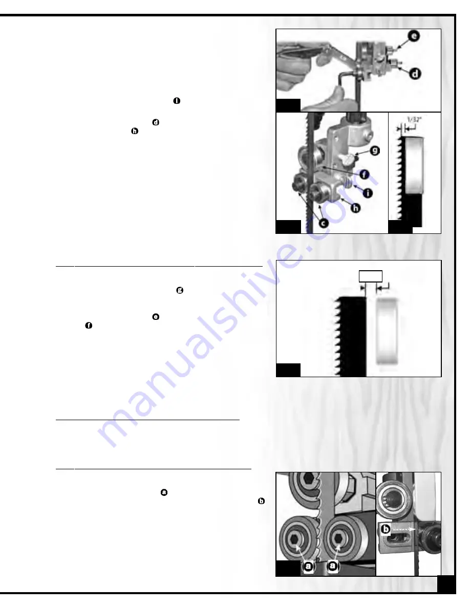
Loosen the upper thumb screw 

. (Fig. 33)

2.

Turn the micro adjust nut 

(Fig.32) to move the thrust bea- 

ring 

(Fig. 33) in or out until the bearing is 1/64” behind 

the back edge of the blade (Fig. 35), then tighten the thumb
screw.

2.

Place a feeler gauge between one of the bearings and
the blade and tighten the Allen bolt until there is a 0.02" 
gap left between the blade guide and the blade. (See Fig. 32)

3.

Repeat step 2. for the other guide on the other side of the
the blade.

4.

Loosen the lower thumb screw 

. (See Fig. 33)

5.

Turn the micro adjust nut 

(See Fig. 32) to move the guide 

bearing assembly 

(See Fig. 33)  in or out until the guides 

are at least 1/32” behind the blade teeth. (See Fig. 34)  The 
guides must remain behind the blade teeth to prevent da-
mage to the blade.

6.

Tighten the thumb screw to lock the guide bearing assem-
bly in position.

Fig. 32

1/64"

Fig. 35

POSITIONING THE LOWER BLADE GUIDES AND THRUST BEARING

The lower blade guides and thrust bearing perform the same function as the upper blade guides and thrust
bearing except they do so after the blade has contacted the stock being cut.

Adjust the positioning of the lower blade guide as follows:

1.

Loosen the two Allen bolts  

and slide the two blade gui-

des along the elongated hole in the mounting bracket 
toward the blade. (Fig. 36)

2.

Place a feeler gauge between one of the bearings and
the blade and tighten the Allen bolt until there is a 0.02" 
gap left between the blade guide and the blade.

Fig. 33

Fig. 34

Fig. 36

23

Summary of Contents for 90-125 M1

Page 1: ...lade tension lever SPECIFICATIONS WHEEL SIZE 13 7 8 353 mm WHEEL SPEEDS 2 495 825 RPM MAXIMUM BLADE WIDTH 3 4 19 mm MINIMUM BLADE WIDTH 1 8 3 2 mm BLADE LENGTH 93 1 2 2375 mm BLADE SPEEDS 2 1800 3000...

Page 2: ...future reference Disclaimer The information and specifications in this manual pertain to the unit as it was supplied from the factory at the time of printing Because we are commit ted to making const...

Page 3: ...der our Standard 2 year Limited Warranty or under our Limited Lifetime Warranty all defective parts components or machinery must be returned freight or postage prepaid to General International or to a...

Page 4: ...nded adjustments 16 Adjusting the 90 table stop and re aligning the angle pointer 16 Tilting the table 16 Removing installing the blade 17 Blade clearance 17 Blade selection 18 Adjusting blade tension...

Page 5: ...against the table 17 Do not work on long stock without adequate sup port on the out feed end of the table 18 If using a power feeder stop the feeder before stop ping the bandsaw 19 Do not push or for...

Page 6: ...cle Do not attempt to modify the plug or remove the 3rd prong grounding pin from the plug to make it fit into an old 2 hole wall socket or extension cord If an adaptor plug is used it must be attached...

Page 7: ...KNOB UPPER BLADE GUIDE LOCK KNOB BLOWER DEVICE TABLE INSERT MITER GAUGE TABLE ALIGNMENT PIN FRONT RAIL DUST PORT BASE CABINET LOWER WHEEL COVER DOOR TABLE TILT LOCK KNOB FENCE LOCK KNOB FENCE ON OFF S...

Page 8: ...4 FLAT WASHER 8 HEX NUTS 4 SCREW 2 HEX HEAD BOLT LONG 1 5 MM ALLEN KEY 1 3 MM ALLEN KEY 1 10 MM COMBINATION WRENCH 1 Carefully unpack and remove the unit and its components from its shipping containe...

Page 9: ...THE SHOP This machine should be installed and operated only on a solid flat and stable floor that is able to support the weight of the bandsaw 224 LBS 102 kg and the operator Using the dimensions sho...

Page 10: ...space for the miter gauge and replacement blades The bandsaw is heavy Do not over exert The help of an assistant will be needed for the following step Do not grip the bandsaw by the lower wheel cover...

Page 11: ...r wheel housing 4 Tighten loosely using a 12 mm open end wrench and 12 mm socket 5 Thread a nut onto the longer table stop bolt and screw the bolt into the hole on the rear tab of the table tilt brack...

Page 12: ...the table tilt bracket Note If the long bolts have moved out of position have an assistant tap them into place with a screw driver 6 Thread the two lock knobs onto the long bolts now protruding from...

Page 13: ...k knobs to secure the fence on the bracket 5 Lock the rip fence against the left side of the blade and check that the pointer is aligned with the zero on the left part of the tape 6 If the pointer doe...

Page 14: ...through the sawblade with reduced risk of injury to the hands A flexible blower tube which connects to the motor can be positionned so as to direct air againt the blade for pre venting accumulation o...

Page 15: ...ecting to a power source 2 Uncoil the power cord and plug it into an appro priate outlet refer back to section Electrical Re quirements and make sure all requirements and grounding instructions are fo...

Page 16: ...e pointer to the 0 point on the scale Then re tighten the screw to secure the pointer in place Never adjust the table angle while the bandsaw is run ning Turn off power first 1 Loosen the two lock kno...

Page 17: ...elongated hole in the mounting bracket as far away as possible from the blade 3 Tighten the two Allen bolts to lock the blade guides in po sition Move the upper thrust bearing back See Fig 21 1 Loose...

Page 18: ...blades made from high carbon steel can be purchased in a variety of widths from your General International dealer under the following parts numbers 90125 B14 1 4 6 TPI blade thickness 0 65 mm 90125 B3...

Page 19: ...e Hold it firmly with one hand as you remove the twist ties Slowly separate the coils of the blade until it unravels into one hoop Proper installation Improper installation Fig 25 Determining ideal bl...

Page 20: ...e and damage the blade tension mechanism 1 Pull the tension lever down for quick blade tension ning 2 Refering to the blade tension gauge set the blade tension to correspond with the width of the blad...

Page 21: ...ans centering the blade on the wheels Ideally the blade should stay relatively centered on both the upper and lower wheels Fig 28 Due to natural variations in castings blade thickness or density and t...

Page 22: ...ADJUSTING THE BLADE GUARD FOR DEPTH OF CUT 1 8 1 4 The blade guard can be moved up or down to accommodate the height of the work to be cut To prevent the blade which is flexible and which would not ot...

Page 23: ...t until the guides are at least 1 32 behind the blade teeth See Fig 34 The guides must remain behind the blade teeth to prevent da mage to the blade 6 Tighten the thumb screw to lock the guide bearing...

Page 24: ...n height High speed is best for cutting soft woods under 4 in height or hard woods under 2 in height Note If wood starts to burn at high speed stop and change to the lower speed setting To change the...

Page 25: ...5 Adjust lower blade guides and thrust bearing CHECKLIST BEFORE STARTING These additional safety measures should be be included in your checklist 6 Make sure all the blade guards are in place 7 Make...

Page 26: ...tentially causing serious injuries 5 Pull the switch toward you to start the bandsaw Note The yellow safety key must first be inserted into the switch 6 Align the cutting line on your workpiece with t...

Page 27: ...o change a cut turn the workpiece and cut your way out through the waste material area When cutting long curves make relief cuts as you go along CUTTING CIRCLES 1 Adjust the blade guard assembly to 1...

Page 28: ...h as General International Top Saver item GC 010 See Section Recommended optional accessories for your bandsaw To avoid eye injury from blowing debris wear safety goggles when blowing out sawdust PERI...

Page 29: ...e thrust bearing and mounting shaft 6 Use C ring pliers to remove the C ring and slide the bearing off the shaft FRONT VIEW 7 Install a new bearing on the mounting shaft 8 Re install the C ring 9 Put...

Page 30: ...osen the Phillips head screw 2 Slide the brush slightly down along the mounting hole so that a fresh stiffer part of the hairs touches the wheel tire 3 Tighten the screw to lock the brush in position...

Page 31: ...l table Includes 2 1 2 T style rip fence and rails and a curved resaw attachment Mobile Base 50 025 Easily roll your bandsaw anywhere in your shop Load capacity 500 LBS Wheels lock when equipment is i...

Page 32: ...32 NOTES...

Page 33: ...3 21 157 105 133 11 7 112 104 103 113 114 18 17 3 95 96 94 92 93 8 9 1 81 10 59N 60N 61N 155 6 71 72 5 126 125 127 4 156 154 153 150 62 73 54 70 55 123 147 56 149 55 135A 63 64 2 58 146 145 158 28 30...

Page 34: ...87 12 78 77 75 77 74 13 14 67 130 79 80 82 66 76 83 78 84 57 58 85 65 86 67 134 68 69 84 83 85 67 144 99 88 90 89 91 140 142 141 43 33 45 46 47 48 35 36 37 38 31 34 32 81 42 39 40 41 137A 138A 128 129...

Page 35: ...RE NUT 3 8 1 90125 26 26 TENSIONING SHAFT 302L 1 90125 27 27 BLADE TENSION ADJUSTMENT KNOB SK 62xM8 1 90125 28 28 SPRING PIN 3x20L 1 90125 29 29 WING NUT 5 16 1 90125 30 30 TRACKING ADJUSTMENT KNOB 5...

Page 36: ...2 90125 78 78 HEX BOLT 5 16x1 1 4 2 90125 79 79 POINTER MY 2000P 1 90125 80 80 LOCK WASHER M5 1 90125 81 81 FLAT WASHER 3 8x19x2T 3 90125 82 82 SCALE 450 1 90125 83 83 TRUNNION 2 90125 84 84 TRUNNION...

Page 37: ...3 8 90125 133 133 HEX NUT 5 16 4 90125 134 134 BLADE GUARD SCALE 1 90125 135A 135A 90 BLOWER ELBOW 1 90125 136A 136A BLOWER TUBE 1 8PTX480L 1 90125 137A 137A STRAIN RELIEF ACC 2 5 3 90125 138A 138A FL...

Page 38: ...64 164 POWER CORD HOOK 2 90125 165 165 FLANGE SCREW 3 16x1 2 2 90125 166 166 TERMINAL P3B 1 90125 168 168 BEARING SHAFT 1 90125 169 169 WAVE WASHER 1 90125 170 170 RIP FENCE ASSEMBLY 1 90125 200 200 C...

Page 39: ...2 MM 1 90125 170 06 LOCK KNOB 1 4 2 90125 170 07 HEX HEAD BOLT 1 4 X 1 3 4 2 90125 170 08 PHILLIP HEAD SCREW M3 X 6 4 90125 170 09 LOCK KNOB 5 16 X 1 1 90125 170 10 HEX HEAD BOLT M6 X 15 2 90125 170...

Page 40: ...2 CAPACITOR TUBE 1 90125 106A 13 13 CAPACITOR COVER 1 90125 106A 14 14 CENTRIFUGAL SWITCH SET 1 90125 106A 15 15 TERMINAL 2 90125 106A 16 16 STRAIN RELIEF 1 90125 106A 17 17 TUBE 1 90125 106A 18 18 TU...

Page 41: ...90125 106B 05 5 BLOWER COVER 1 90125 106B 06 6 LOCK WASHER 3 90125 106B 07 7 SCREW 3 90125 106B 08 8 HOSE BARB 2 90125 106B 09 9 BLOWER HOSE 1 90125 106B 10 10 SPONGE 1 90125 106B 11 11 COVER 1 90125...

Page 42: ...al number of the machine and part number Also a brief description of each item and quantity desired 8360 Champ d Eau Montreal Quebec Canada H1P 1Y3 Tel 514 326 1161 Fax 514 326 5565 Parts Service Fax...

Reviews: