background image

SETUP & OPERATION MANUAL

Version 

#

1_Revision 

#

2 - November 2015 

© Copyright General International

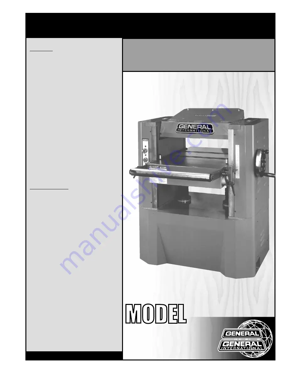
20” SINGLE SURFACE PLANER

MODEL

#

30-360 

#

30-360HC* 

FEATURES

Positive gear design for quick and accurate 

table adjustments.
5” dust collection hood.
Cast-iron table and head.
Four cutter knives result in easier cutting and 

longer motor life, (helical cutter head model 

available: #30-360HC).
Built-in table rollers reduce friction. 
Large 8” handwheel quickly adjusts table 

height.
Comes with magnetic safety switch.
Graduated scale in both inches and metric to 

indicate workpiece thickness.
Anti-kickback fingers at the front of the infeed 

roller to ensure maximum operator safety.
Vertical adjustment handle for table rollers.
Equipped with a sectioned infeed roller and a 

rubber outfeed roller.
One front-mounted exterior table roller.

SPECIFICATIONS

•  Table size 


  32” x 20” (813 x 508 mm)
•  Maximum planing width 

  20” (508 mm)
•  Min/Max thickness of stock 

  3/16” (5 mm) / 8” (204 mm)
•  Minimum length of stock 

  8 1/4” (210 mm)
•  Maximum cutting depth (full width) 

  1/8” (3 mm)
•  Maximum cutting depth (width 8 1/2” or less) 

  1/4” (6 mm)
•  Cutter head diameter 

  3 3/4” (97 mm)
•  Cutter head speed 

  4500 rpm
•  Feed speeds 

  (2) 22 & 28 fpm
•  Cuts per inch (not applicable for HC model) 

  68.17 at 22 fpm & 53.5 at 28 fpm
•  Number of knives / Inserts  

  4 - 30-360 / 58 - 30-460HC
•  Base dimensions (l x w) 

  36” x 22” (914 x 559 mm)
•  Motor  

  M1: 7 1/2 HP, 220 V, 1 Ph, 31 A 

  M2: 7 1/2 HP, 220 V, 3 Ph, 20 A 

  M3: 7 1/2 HP, 600 V, 3 Ph, 10 A
•  Weight 

  1392 lbs (633 kg) - 30-360 

  1397 lbs (635 kg) - 30-360HC

*With helical cutter head

Summary of Contents for 30-360

Page 1: ...erator safety Vertical adjustment handle for table rollers Equipped with a sectioned infeed roller and a rubber outfeed roller One front mounted exterior table roller SPECIFICATIONS Table size 32 x 20...

Page 2: ...from knowledgeable and qualified sources that it is safe to do so Once you ve read through these instructions keep this manual handy for future reference DISCLAIMER The information and specifications...

Page 3: ...rd 2 year Limited Warranty or under our Limited Lifetime Warranty all defective parts components or machinery must be returned freight or postage prepaid to General International or to a nearby distri...

Page 4: ...s 13 16 Basic principles of planing 13 Selecting boards suitable for planing 13 Rated limits of this planer 13 Adjusting the depth of cut 14 Adjusting feed speed 14 Checklist before starting 14 Planin...

Page 5: ...objects be fore planing Make sure that any stock you plane is clean and free of any dirt nails staples tiny rocks or any other foreign objects that may damage the planer knives Only process natural s...

Page 6: ...cal connections must be made in accordance with all local codes and regulations CIRCUIT CAPACITY Make sure that the wires in your circuit are capable of handling the amperage draw from your machine as...

Page 7: ...ME B EXTENSION ROLLER C ON OFF SWITCH D MAIN TABLE E DUST CHUTE F GRADUATED SCALE G FEED SPEED ADJUSTMENT KNOB H DEPTH OF CUT ADJUSTMENT HANDWHEEL I ECCENTRIC BLOCK J EXTENSION ROLLER LOCK LEVERS 2 K...

Page 8: ...O RETENTION RING 4 A B C D K L KNIFE SETTING JIG M N O E F J G H I ADDITIONAL REQUIREMENTS FOR SET UP A 0 02 FEELER GAUGE B 0 004 FEELER GAUGE C GAUGE BLOCK D STRAIGHT EDGE B A D 0 0 2 0 0 0 4 C This...

Page 9: ...fic either passing shop visitors or other shop workers or other tools or machinery ESTABLISHING A SAFETY ZONE For shops with frequent visitors or multiple operators it is advisable to establish a safe...

Page 10: ...and fittings not in cluded Check that all connections are sealed tightly to help minimize airborne dust If you do not already own a dust collection system consider contacting your General Internation...

Page 11: ...ch on this machine is equipped with an overload protection feature To prevent an elec trical overload from damaging the motor in the event of a spike in line voltage or amperage draw the internal over...

Page 12: ...the rollers at the desired height C B A IMMOBILIZING THE MACHINE G F Machine vibration during operation may cause the machine to move particularly when installed on un even surfaces The pads F and anc...

Page 13: ...can be ejected from the machine at high speed and cause serious injury or damage cutter knives Make sure to remove all such foreign objects from the wood before running it through the planer Select lu...

Page 14: ...ADJUSTING THE DEPTH OF CUT The depth of cut is adjustable by using the handwheel A Remind that the maximum depth of cut on full width planing is 1 8 and lowering the head assem bly It is recommended...

Page 15: ...ler to auto matically feed the board through the planer 8 Steptotherearofthemachineandrecovertheplaned board on the outfeed table once it has cleared the outfeed roller and has stopped advancing GRAIN...

Page 16: ...cases impor tant maintenance transport handling no further adjustments are required If adjustments are required follow these procedures 1 Disconnect the machine from the power source 2 Place the gauge...

Page 17: ...der the end of the infeed roller A as shown Loosen the nut G turn the screw H until the roller touches the top of the block and then re tighten the nut G Repeat for the other end 4 Place the block E u...

Page 18: ...ted at each end table roller under the table then turn the bolts C to the direction required to raise or lower the roller Retighten the bolts B and repeat with the other roller Note Always make sure t...

Page 19: ...ion INSPECTING CUTTER HEAD KNIVES INSERTS Cutter head knives blades inserts are installed in the planer at the factory With usage and normal wear over time it will eventually become necessary to repla...

Page 20: ...3 Remove the chip deflector using a 4 mm Allen key 4 Position one of the four knives on top by manually turning the cutter head belt and setting the gauge B on the cutter head as shown C RIGHT SIDE L...

Page 21: ...inserts on hand and ready for use when needed 1 Refer to section Inspecting cutter head knives and perform steps 1 to 3 before following the in structions below 2 Turn the cutter head pulley by hand t...

Page 22: ...butor under part 30 443 sold by sets of ten NOTE THE DISASSEMBLY OF THE CUTTING HEAD IS NOT RE QUIRED FOR THIS OPERATION THE IMAGE ABOVE IS FOR IL LUSTRATION ONLY A B 1 Using one of the two supplied A...

Page 23: ...ten both the screw and nut simultaneously Do not thread the nut onto the screw before tightening the screw into the threaded hole in the cutter head REPLACING THE GEAR BOX OIL EVERY 2500 HOURS OF OPER...

Page 24: ...E ONCE A MONTH Remove old lubrificant and dust deposits by wiping with a dry rag then apply generous dabs of the lubricant required B SLIDING SURFACES ALL PURPOSE OIL ONCE A MONTH C CHAINS ALL PURPOSE...

Page 25: ...st particles or residue left behind A ALIGNING THE BELTS 1 Remove the left panels using a 4 mm Allen key B 2 Using a straight edge C verify that the pulleys are properly aligned To align the pulleys p...

Page 26: ...nuts D against the motor mount ing plate 6 Close the motor access door To change the belts 7 Remove the left panels A B 8 Remove the nuts E 9 Place a piece of wood under the motor base as shown F 10 S...

Page 27: ...llel to the table set of 2 Item 30 050 DIAL GAUGE MICROMETER FOR PLANER KNIFE ALIGNMENT Precision built easy to ad just mounted on enamel finished alloy steel De signed to rest squarely on the cutter...

Page 28: ...15 31 36 35 34 33 32 41 40 31 39 38 37 57 57 58 59 29 D 23 56 40 30 15 34 40 33 32 30 89 90 77 78 34 63 64 66 65 62 67 68 69 67 67 93 71 67 73 74 75 79 40 30 87 88 75 73 67 81 83 83 84 85 72 86 19 20...

Page 29: ...18 110 111 112 113 114 101 119 120 121 122 123 124 125 104 105 126 127 128 129 130 131 118 153 117 118 134 102 138 140 135 126 136 137 139 141 104 106 146 133 149 143 144 145 147 153 117 118 152 151 1...

Page 30: ...68 169 170 171 157 172 173 175 174 178 159 179 180 181 162 176 156 177 183 184 185 167 182 191 177 192 161 156 183 186 187 188 189 162 159 159 158 196 163 197 160 201 200 198 199 202 203 155 206 205 2...

Page 31: ...6 223 218 220 221 215 212 210 217 227 236 234 235 233 237 214 231 232 211 231 230 229 224 225 238 239 209 241 242 240 245 241 209 222 248 251 252 249 250 254 255 258 219 263 213 260 266 226 226 266 26...

Page 32: ...HC 1 30360 49 BEARING 6006 2NSE 1 30360 50 GEAR 1 30360 51 SET SCREW M10X1 5PX12L 4 30360 52 SPACER 2 30360 53 RUBBER PIN 120 30360 54 INFEED ROLLER 20 30360 55 INFEED ROLLER SHAFT 1 30360 56 SPROCKET...

Page 33: ...0360 167 NUT M8X1 25P 6 30360 168 SET SCREW M8X1 25PX40L 6 30360 169 GIB 2 30360 170 NUT M8X1 25PX16L 2 30360 171 LEAD PLATE 2 30360 172 HEX HEAD BOLT M10X1 5PX50L 2 30360 173 FIXING POINT 2 30360 174...

Page 34: ...MOTOR M2 7 5HP 220V 3PH 1 MOTOR M3 7 5HP 600V 3PH 1 30360 258 MOTOR CORD 10AWG 3CX0 5M 1 MOTOR CORD 12AWG 4CX0 5M 1 30360 260 CLAMP COLLAR 2 30360 261 BELT A74 3 30360 262 SUPPORT SHAFT 2 30360 263 S...

Page 35: ...WIRING DIAGRAM 30 360 M1 30 360M2 30 360M1 35...

Page 36: ...WIRING DIAGRAM 30 360 M2 30 360M2 30 360M3 36...

Page 37: ...WIRING DIAGRAM 30 360 M3 30 360M3 37...

Page 38: ...Follow us 8360 Champ d Eau Montreal Quebec Canada H1P 1Y3 Tel 514 326 1161 Fax 514 326 5565 Parts Service 514 326 5555 Order Desk orderdesk general ca www general ca...

Reviews: