General International 90-290 Setup & Operation Manual Download Page 19

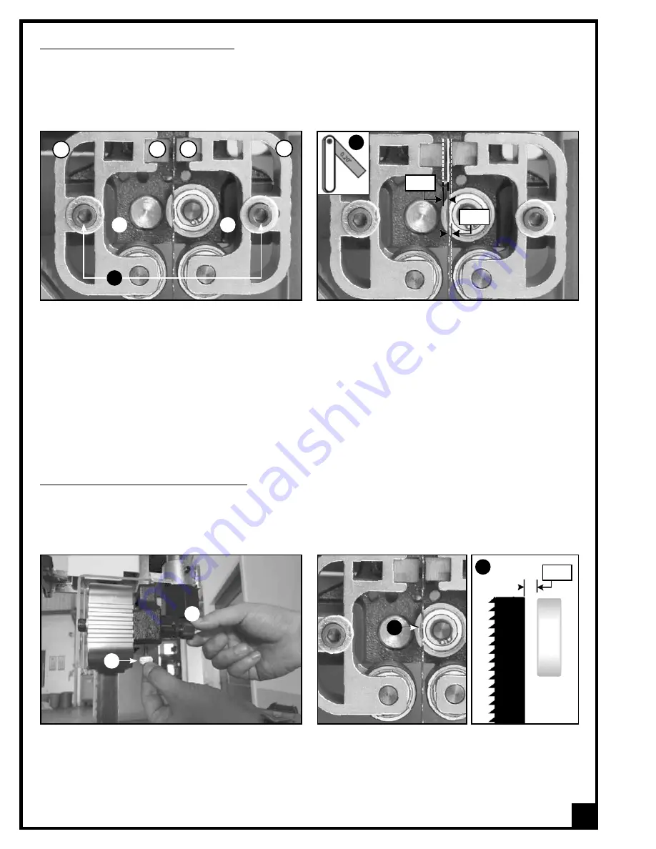
POSITIONING THE UPPER/LOWER THRUST BEARING

The thrust bearings keep the blade from moving back and out of position when the work is being fed into the blade 
and must be very close to the back of the blade to prevent damage to the blade during cutting. 

Adjust the positioning of the upper and lower thrust bearings as follows:

A

B

F

C

C

D

D

E

0.02”

0.02”

1.  

Using a 6 mm Allen key, loosen the two cap screws, 

A.

2. 

Adjust the left and right mounts 

that hold the bakelite blocks 

and guide bearings 

D

 to obtain a space of  


0.02” (the thickness of a sheet of paper) between the blade and blocks & bearings.

Tip: Place a feeler gauge 

C


or  sheet of paper between the blocks & bearings and the blade to make sure there is a 0.02” 

space. 

3. 

Re-tighten the two cap screws 

A

 to lock the mounts in position.

4. 

Repeat steps 1 to 3 with the lower blade guides.

1.  

Loosen thumb screw 

D.

2. 

Turn the adjustment knob 

to move the thrust bearing in or out, until the bearing 

almost touches the blade  


(is 1/64” behind the back of the blade 

G

).

3. 

Re-tighten thumb screw 

D

 to lock the thrust bearing in position.

4. 

Repeat steps 1 to 3 with the lower thrust bearing.

POSITIONING THE UPPER/LOWER BLADE GUIDES

The space between each bearing and the blade must not exceed 0.02” (the thickness of a sheet of paper ). If less 
space is left, the blade will get stuck or jammed between both bearings. Too much friction will cause blade to over-
heat and break. 

Adjust the positioning of the blade guides as follows:

D

E

G

19

1/64”

B

Summary of Contents for 90-290

Page 1: ...nd dual miter slots in table for stable cross cuts on either side of the blade Deluxe Excalibur bandsaw rip fence system with curved guide block and a 6 wooden resaw auxiliary fence Onboard storage mo...

Page 2: ...manual handy for future reference Disclaimer The information and specifications in this manual pertain to the unit as it was supplied from the factory at the time of printing Because we are com mitte...

Page 3: ...d 2 year Limited Warranty or under our Limited Lifetime Warranty all defective parts components or machinery must be returned freight or postage prepaid to General International or to a nearby distrib...

Page 4: ...stalling the blade 14 Blade Clearance 14 Adjusting blade tension 16 Adjusting blade tracking 17 Adjusting the upper lower blade guides and thrust bearig 28 Positioning the upper and lower blade guide...

Page 5: ...lications and limita tions as well as potential hazards General International disclaims any real or implied warranty and hold itself harmless for any injury that may result from the improper use of it...

Page 6: ...h installation situation is unique this bandsaw is supplied without a power cord or plug The installation of an appropriate power cord and plug must be performed by a qualified electrician The ma chin...

Page 7: ...E GUIDE SYSTEM G MITER GAUGE H RIP FENCE I TABLE J LOWER WHEEL COVER DOOR LOCK KNOB K FOOT BRAKE REAR VIEW L LIFTING EYEBOLTS MODEL 90 380 ONLY M BLADE TRACKING ADJUSTMENT HANDWHEEL N BLADE TENSION SC...

Page 8: ...urfaces as many solvent based products will remove paint To prevent rust apply a light coating of paste wax or use regular applications of any after market surface pro tectant or rust inhibitor CLEAN...

Page 9: ...17 5 8 for the 90 290 and 21 5 8 for the 90 380 For cutting thicker stock or for resawing the maximum depth of cut B or max workpiece height is 12 for the 90 290 and 16 for the 90 380 An adjustable r...

Page 10: ...cumbered and unobstructed by foot traffic either passing shop visitors or other shop workers or other tools or machinery Model 90 380 Model 90 290 39 357 8 743 8 457 8 373 4 805 8 SERIOUS PERSONAL INJ...

Page 11: ...ht face of the rip fence by sliding the nut of the 3 screw nut assemblies C in the T slot on the right face of the rip fence D Using a screwdriver tighten the screws to secure the wooden fence against...

Page 12: ...uicker than normal Under normal working conditions the red stop button should be used as the primary stop mechanism Continuously using the foot brake as the primary stop mechanism will lead to prematu...

Page 13: ...90 position automatically without further adjustments and scale reading for any angle other than 0 will also be accurate 1 Loosen table locking lever A and table lock knob B 2 Place a combination squa...

Page 14: ...an turn much tighter corners for cutting more intricate work A Common causes of blade breakage Poor blade guide or support bearing alignment and adjustment Forcing or twisting a wide blade around a sh...

Page 15: ...hang the blade on a hook in a safe dry place in your workshop if it will be re used or dispose of it safely if it is worn or damaged BEWARE OF THE BLADE POPPING OPEN B A PROPER INSTALLATION IMPROPER...

Page 16: ...rm ed using less tension This bandsaw is equipped with a blade tension scale which can be used as a reference for the ideal setting with various blade widths To adjust blade tension proceed as follows...

Page 17: ...eel B A B 3 mm 1 8 To adjust the blade tracking 1 Open the upper wheel cover door then rotate the wheel slowly forward by hand A and check through the win dow of the upper wheel the position of the bl...

Page 18: ...position when the work is being fed into the blade and must be very close to the back of the blade to prevent damage to the blade during cutting Note Before adjusting the upper and lower blade guide...

Page 19: ...er between the blocks bearings and the blade to make sure there is a 0 02 space 3 Re tighten the two cap screws A to lock the mounts in position 4 Repeat steps 1 to 3 with the lower blade guides 1 Loo...

Page 20: ...f position during cutting and to reduce risks of injuries a minimum amount of blade should be exposed The blade guard should be set 1 8 1 4 above the work piece B to prevent the blade from flexing out...

Page 21: ...en hex bolt C to move the laser L bracket D left or right as needed until the beam overlaps the blade ALWAYS TURN ON THE DUST COLLECTOR BEFORE STARTING THE SAW AND ALWAYS STOP THE SAW BEFORE TURNING O...

Page 22: ...AND REMOVE ANY JEWELRY WATCHES RINGS BRACELETS OR ANYTHING THAT COULD GET STUCK IN THE MOVING PARTS OF THE BANDSAW POTENTIALLY CAUSING SERIOUS INJURIES 4 Push the green ON button to start the bandsaw...

Page 23: ...guard assembly to 1 8 above the workpiece 2 Use both hands while feeding the work into the blade Hold the workpiece firmly against the table Use gentle pressure Do not force the work Allow the blade t...

Page 24: ...ge 4 Do not allow dirt pitch or gum to build up on the table blade guide thrust bearings Clean as needed with gum and pitch remover Note Do not immerse the bearings in the gum and pitch remover 5 To p...

Page 25: ...11 Install a new bearing on the shaft then re install the C ring J K L F F 12 Repeat steps 1 to 7 in reverse order to re install the blade guide and thrust bearing assembly Repeat steps 1 to 12 with t...

Page 26: ...o remove the tire from the groove on the wheel then install a new tire Note When replacing the tires stretch them around the wheels but do not glue them on LOWERING THE WHEEL BRUSH A A REPLACING LOWER...

Page 27: ...dsaw For more information about our products please visit our website at www general ca DUST COLLECTORS Dust collectors contribute to a cleaner more healthful workshop environment We offer a wide sele...

Page 28: ...A 56 57 58 59 50 51 52 59 60 79 28 62 63 42 44 45 46 64 65 61 4 4 47 66 67 41 40 39 77 76 4 75 74 23 73 4 23 60 71 61 60 70 4 60 69 59 60 61 56 60 60 59 61 60 72 68 67 66 80 28 81 82 83 84 85 86 87 88...

Page 29: ...8 108 7 50 51 41 90 129 123 122 121 120 115 116 50 132 41 40 111 117 110 112 119 141 118 113 114 1 115 116 116 115 115 111 117 121 120 131 130 50 51 7 50 119 118 141 112 113 132 122 123 124 48 116 50...

Page 30: ...0 4 5 50 212 228 39 40 41 205 60 204 203 50 227 202 213 214 215 60 23 217 218 225 63 224A 41 40 216 73 51 50 55 219 223 222 48 221 229 5 229 4 229 1 229 2 229 3 229 6 229 230 231 232 233 236 235 234...

Page 31: ...0290 26 UPPER DOOR 1 27 90290 27 HINGE PIN 4 28 90290 28 HEX NUT 3 16 6 29 90290 29 WINDOW 1 30 90290 30 CAP SCREW 1 4 X3 8 2 31 90290 31 LOWER DOOR 1 32 90290 32 LOWER WHEEL 1 33 90290 33 PULLEY 1 34...

Page 32: ...CONTACTOR PLATE 1 82 90290 82 MOUNTING PLATE 1 83 90290 83 STRAIN RELIEF 2 84 90290 84 HANDLE 1 85 90290 85 PHILLIPS HEAD SCREW 1 4 X3 4 2 86 90290 86 STOP BUTTON 1 87 90290 87 ON BUTTON 1 88 90290 8...

Page 33: ...TENSION BRACKET R 1 147 90380 147 BLADE GUIDE EXTENSION BRACKET L 1 202 90290 202 HEX BOLT 5 16 X1 1 203 90290 203 LOCK KNOB 1 204 90290 204 ANGLE ADJUSTMENT BRACKET 1 205 90290 205 ANGLE ADJUSTMENT B...

Page 34: ...290 229M6 FLAT HEAD SCREW 3 16 24UNC 3 8 L 1 229 M7 90290 229M7 T SLOT WASHER 1 229 M8 90290 229M8 GUIDE BAR 1 229 M9 90290 229M9 STOP 1 229 M10 90290 229M10 POINTER 1 229 M11 90290 229M11 SET SCREW 3...

Page 35: ...90290 A6 T TYPE BASE 1 A7 90290 A7 FLAT WASHER 5 16 12 A8 90290 A8 LOCK NUT 5 16 4 A9 90290 A9 LOCK WASHER 8MM 4 A10 90290 A10 HEX BOLT 5 16 X1 5 A11 90290 A11 PUSHER 1 A12 90290 A12 LINK PLATE 1 A13...

Page 36: ...2 20 32 19 20 33 35 37 38 39A 40A 41A 23 34 36 48 56 57 58 59 4 3 2 59 60 79 28 62 63 44 45 46 64 65 61 54 54 47 60 66 67 41 40 39 77 76 23 73 54 75 74 23 73 54 23 60 71 61 60 70 54 60 69 59 60 61 56...

Page 37: ...11 115 115 116 116 115 114 1 113 118 117 119 112 110 117 111 40 41 132 4 116 115 120 121 122 123 129 90 41 3 4 102 108 48 124 125 3 4 126 127 48 136 101 128 133 134 135 48 137 138 139 102 3 4 103 104...

Page 38: ...30 30 45 4 212 228 39 40 41 205 60 204 203 4 227 202 213 214 215 60 23 217 218 225 63 224A 41 40 216 73 23 60 92A 219 223 222 48 221 229 5 229 4 229 1 229 2 229 3 229 230 231 232 233 236 235 234 TABLE...

Page 39: ...171 1 4 1 26 90380 26 UPPER DOOR 1 27 90290 27 HINGE PIN 4 28 90380 28 HEX NUT 3 16 4 29 90290 29 WINDOW 1 30 90380 30 CAP SCREW 1 4 X3 8 2 31 90380 31 LOWER DOOR 1 32 90380 32 LOWER WHEEL 1 33 90380...

Page 40: ...EF 2 84 90290 84 HANDLE 1 85 90380 85 PHILLIPS HEAD SCREW 1 4 X3 4 2 86 90380 86 STOP BUTTON 1 87 90380 87 ON BUTTON 1 88 90380 88 POWER LIGHT 1 89 90290 89 CONTROL PANEL PLATE 1 90 90380 90 BUTTON HE...

Page 41: ...BLADE GUIDE EXTENSION BRACKET L 1 202 90380 202 HEX BOLT 5 16 X1 1 203 90290 203 LOCK KNOB 1 204 90380 204 ANGLE ADJUSTMENT BRACKET 1 205 90290 205 ANGLE ADJUSTMENT BRACKET BASE 1 212 90380 212 TABLE...

Page 42: ...number of the machine and part number Also a brief description of each item and quantity desired 8360 Champ d Eau Montreal Quebec Canada H1P 1Y3 Tel 514 326 1161 Fax 514 326 5565 Parts Service Fax 51...

Reviews: