General International 15-155 M1 Setup & Operation Manual Download Page 8

BASIC FUNCTIONS

This drum sander is designed for surface sanding of flat wooden panels, glue-ups and other natural wood products,
having a minimum length of 5” and up to a maximum width of 13”. The minimum/maximum capacity (workpiece
thickness range), is from 1/4” up to 3 3/4”. This sander is not intended (and should not be used) to sand any mate-
rial other than wood.

BASIC PRINCIPLES OF SANDING

It is always preferable to remove less material per pass and take multiple passes. This can extend sanding belt life,
place less strain on the motor and provide better workpiece finish quality.

Note: To avoid overworking the motor, creating a potential circuit overload, or damaging the sanding drum, do not
force the workpiece against or into the drum. For better finish results and to avoid potential damage to the sander
or the workpiece, let the workpiece feed into the sander at the rate of feed to which the conveyer is set.

Note: As with any other drum or belt sander, depending on the final finish quality you require, some final hand 
sanding may be required.

DO NOT USE THIS SANDER AS A THICKNESS PLANER. NEVER ATTEMPT TO REMOVE MORE THAN THE DEPTH OF THE GRAIN OF THE
SANDING BELT IN ANY SINGLE PASS. TOO MUCH FRICTION WILL CAUSE BELT TO OVERHEAT AND WEAR PREMATURELY, AND, IN
EXTREME CASES, MAY CAUSE BURNS IN THE WORKPIECE.

UNPACKING

Carefully unpack and remove the sander and its components from the shipping crate and check for damaged or
missing items as per the list of contents below.

Note: Please report any damaged or missing items to your General International distributor immediately.
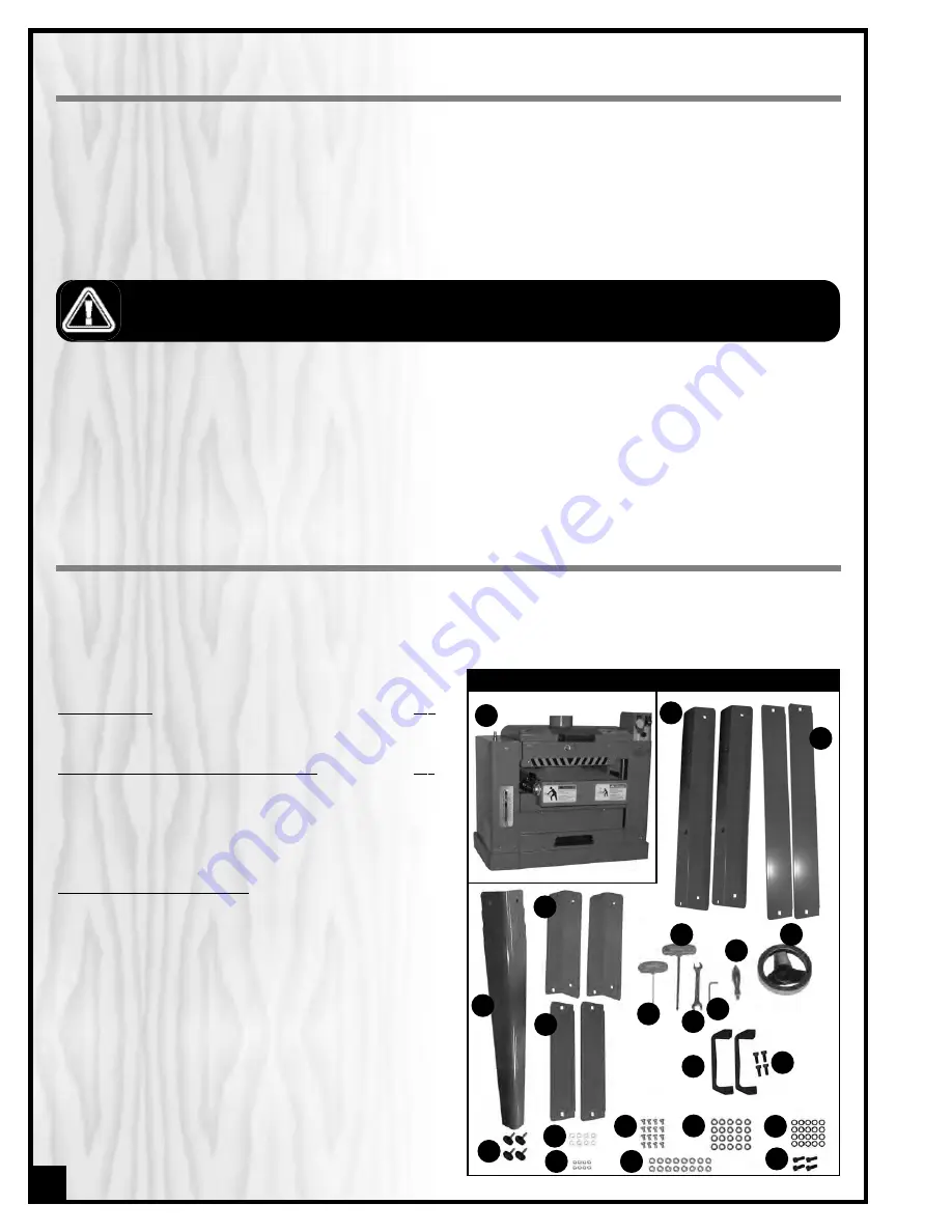
LIST OF CONTENTS 

BOX 1 - SANDER 

QTY

A

-  13” HORIZONTAL SINGLE DRUM SANDER.....................1

BOX 2 - OPEN STAND & OTHER COMPONENTS

QTY

B

-  LONG TOP SHELF ...........................................................2

C

-  LONG CROSS BRACE ....................................................2

D

-  SUPPORT LEG .................................................................4

E

-  SHORT TOP SHELF...........................................................2

F

-  SHORT CROSS BRACE....................................................2

HARDWARE BAG INCLUDING:

G

HAND WHEEL.............................................................................1

H

HAND WHEEL HANDLE..............................................................1 

I

5 MM ALLEN KEY ......................................................................1

J

6 MM T-HANDLE ALLEN WRENCH ............................................1

K

2 MM T-HANDLE ALLEN WRENCH ............................................1

L

12- 14 MM OPEN END WRENCH..............................................1

M

CARRYING HANDLE ..................................................................2

N

CAP SCREW...............................................................................4

O

-  LEVELING FOOT .............................................................4

-  FLAT WASHER..................................................................8

Q

-  HEX NUT .........................................................................8

R

-  SHOULDER BOLT...........................................................16

S

-  HEX NUT .......................................................................16

T

- LOCK WASHER .............................................................20

U

-  FLAT WASHER................................................................20

V

-  CAP SCREW ...................................................................4 

D

O

P

Q

R

S

T

U

V

BOX 1

A

H

G

I

K

J

L

M

N

BOX 2

B

C

E

F

Summary of Contents for 15-155 M1

Page 1: ...hes and metric to indicate sanding thickness Independent switches with removable safety key for both conveyor motor and main motor 4 dust outlet MAXIMUM SANDING WIDTH 13 330 MM MAXIMUM SANDING THICKNE...

Page 2: ...for future reference Disclaimer The information and specifications in this manual pertain to the unit as it was supplied from the factory at the time of printing Because we are commit ted to making co...

Page 3: ...der our Standard 2 year Limited Warranty or under our Limited Lifetime Warranty all defective parts components or machinery must be returned freight or postage prepaid to General International or to a...

Page 4: ...or to your shop made bench 10 CONNECTING TO A DUST COLLECTOR 10 BASIC ADJUSTMENTS CONTROLS 11 Connecting to a power source 11 ON OFF power switches 11 Drum motor ON OFF switch 11 Conveyor motor ON OF...

Page 5: ...ating 10 Keep hands well away from the sanding belts and all moving parts Use a brush not hands to clear away sanding dust 11 Be sure sanding belts are securely installed on the sanding drums 12 Do no...

Page 6: ...st and a power failure still occurs contact a qualified technician or our service department BEFORE CONNECTING THE MACHINE TO THE POWER SOURCE VERIFY THAT THE VOLTAGE OF YOUR POWER SUPPLY CORRESPONDS...

Page 7: ...IGHT ADJUSTMENT HAND WHEEL B DUST OUTLET C CONVEYOR MOTOR START STOP SWITCH WITH SAFETY KEY D CONVEYOR BELT SPEED ADJUSTING KNOB E SANDING DRUM MOTOR POWER SWITCH F CONVEYOR BELT G GRADUATED DEPTH SCA...

Page 8: ...ality you require some final hand sanding may be required DO NOT USE THIS SANDER AS A THICKNESS PLANER NEVER ATTEMPT TO REMOVE MORE THAN THE DEPTH OF THE GRAIN OF THE SANDING BELT IN ANY SINGLE PASS T...

Page 9: ...ght adjustment hand wheel onto the shaft located on the top left end of the sander B The slots in the hand wheel must be aligned with the spring pin on the shaft A A B C B A ASSEMBLE THE STAND Note If...

Page 10: ...e measurements shown at B to drill corresponding holes into your shop built stand Or carefully position the sander upon your bench and with a pencil trace the four holes onto the stand surface B A 12...

Page 11: ...CTING TO A POWER SOURCE DRUM MOTOR ON OFF SWITCH The ON OFF SWITCH A located on the left end of the control box controls the drum motor To start the drum motor insert the yellow safety key B and lift...

Page 12: ...a reference but it is not intended for high precision measurements B WORK PIECE DRUM DO NOT CONVEYOR BELT DO Effect exaggerated for clarity C CHANGING FEED SPEED The conveyor speed ranges from 6 to 2...

Page 13: ...face of a workpiece across its width caused by a variation in the sanding depth during a given pass it is important to keep the workpiece level on the feed table until it has completely cleared contac...

Page 14: ...ss the workpiece again raising the table not more than 1 8 of a turn at a time Repeat until desired finish quality is achieved Note To avoid overworking the motor creating a potential circuit overload...

Page 15: ...ributor For users who prefer to purchase abrasives in longer uncut rolls or from bulk suppliers the following cutting diagram can be used to assist in cutting the bulk paper to the correct size for th...

Page 16: ...s possible then release the clamp to lock the tab in place 16 TO DO DO NOT TO DO DO NOT TO DO DO NOT 3 Tightly wind the sanding belt around the drum making sure that there are no spaces between the ed...

Page 17: ...right end of the drum This may cause a slight overlap on the last wrap on the drum A and this despite installing the right end of the belt as far into the clamp as it will go In such cases to avoid ha...

Page 18: ...images below A B Max 3 4 LUBRICATION DISCONNECT MACHINE FROM POWER SOURCE BEFORE PERFORMING ANY MAINTENANCE OR LUBRICATION Note Unscrew and remove the front panel A and both side panels B to access th...

Page 19: ...belt and the conveyor belt NEVER OPERATE THE SANDER WITH ANY DAMAGED PART REPLACE A DAMAGED PART AT THE FIRST VISIBLE SIGNS OF DAMAGE REQUIRED MAINTENANCE DRUM MOTOR BELT REPLACEMENT The sanding drum...

Page 20: ...roll your sander anywhere in your shop Load capacity 500 lbs Wheels lock when equi pment is in use Flexible expandable 2 way roller stand Item 50 167S Ideal for use for infeed or outfeed support 20 w...

Page 21: ...21...

Page 22: ...80 110 97 151 150 110 97 151 138 140 169 168 167 170 123 122 82 15 103 76 101 99 99 95 77 76 95 95 99 93 79 96 96 95 95 94 82 94 96 59B 55 54 55 54 58 57 56 96 55 54 53 52 52 56 53 55 54 10 14 13 12...

Page 23: ...7 8 4 4 32 75 76 77 102 9B 9A 100 79 79 100 102 18 49 49 88 104 79 80 105 105 105 47 45 45 46 80 79 104 105 105 45 88 46 47 105 17 5 5 6 18 113 114 113 114 114 114 115 115 129 130S 132 149 99 131S 16...

Page 24: ...2 79 108 80 41 41 42 43 44 110 109 27 26 93 117 77 117 77 93 134 142 135 143 133 76 76 144 146 145 82 24...

Page 25: ...121 121 121 82 80 80 108 82 118 30 80 107 39 105 108 80 31 119 121 120 38 124 25...

Page 26: ...36 37 80 82 82 79 80 106 93 79 80 35 91 92 112 80 82 26...

Page 27: ...5155 024 22300024 FRONT UPPER PANEL 1 15155 025 22300025 DUST HOOD SUPPORT PANEL 1 15155 026 22300026 LEFT COVER PANEL 1 15155 027 22300027 RIGHT COVER PANEL 1 15155 028 22300028 SWITCH BOX 1 15155 02...

Page 28: ...C FLAT WASHER 53 15155 081 S0060510 SCREW 4 15155 082 S0120500 HEX NUT 48 15155 083 S0030580M PHILLIPS HEAD SCREW 4 15155 084 20900069 MICRO ADJUSTMENT SPRING 4 15155 085 S0120500M NYLON NUT 4 15155 0...

Page 29: ...LECTRIC WARNING LABEL 1 15155 140 JG000012 TABLE WARNING LABEL 1 15155 141 JG209002 WARNING LABEL 1 15155 142 JG209004 SPEED LABEL 1 15155 143 IDENTIFICATION PLATE 1 15155 144 S100PG13 STRAIN RELIEF 3...

Page 30: ...ial number of the machine and part number Also a brief description of each item and quantity desired 8360 Champ d Eau Montreal Quebec Canada H1P 1Y3 Tel 514 326 1161 Fax 514 326 5565 Parts Service Fax...

Reviews: