background image

SC800 T3 Operation

SC800 T3 Configuration Menu

076R160-000

SpectraComm 800 T3 Data Service Unit

3-9

Issue 4

Installation and Operation Manual

Alarm Configuration Screens

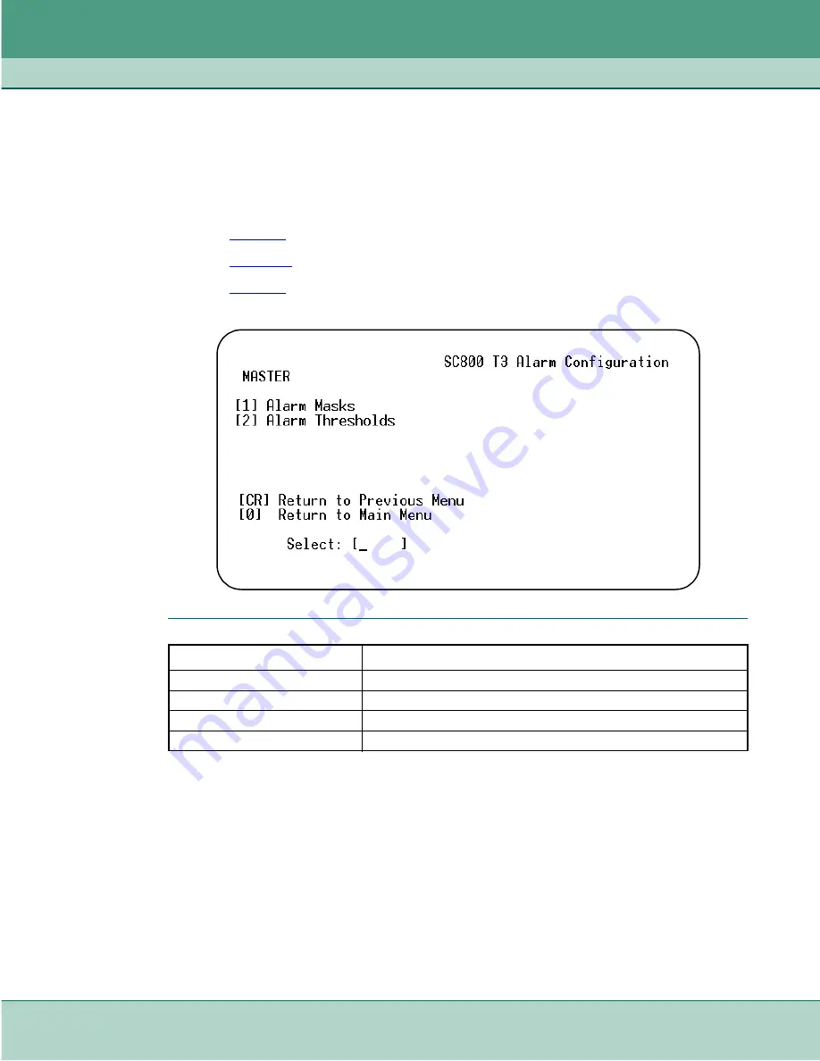
At the SC800 T3 Configuration Menu, type

 3 

to access the Alarm Configuration menu, shown 

below. Selections made at this menu and the associated subscreens determine which alarms the 
DSU will report (Reported) and which are not reported (Masked). The Alarm Thresholds subscreen 
controls the criteria which determine when alarms are to report. Alarm definitions are provided later 
in this chapter.

Table 3-6

 describes the Alarm Configuration menu

Figure 3-2

 describes the Alarm Configuration subscreen.

Table 3-7

 describe the Alarm Thresholds Configuration subscreen.

Table 3-6

Alarm Menu

Selection

Description

[1] Alarm Mask

Advances to the Alarm Mask Configuration subscreen.

[2] Alarm Threshold

Advances to the Alarm Interval Threshold screen.

[CR] Return to Previous Menu

Press Enter (Carriage Return) to return to the Configuration Menu.

[0] Return to Main Menu

Returns to the SC 5001 Main Menu.

Summary of Contents for SpectraComm 800 T3

Page 1: ...The Best Connections in the Business General DataComm 6SHFWUD RPP 33 76 Data Service Unit Installation Operation Manual 076R160 000 Issue 4 May 2012...

Page 2: ...271 Trademarks All brand or product names are trademarks or registered trademarks of their respective companies or organizations Documentation Revision History GDC P N 076R160 000 Related Publications...

Page 3: ...hnical Specifications 1 6 Chapter 2 Installation and Setup Unpacking Instructions 2 1 SpectraComm Shelves and Enclosures 2 2 Hardware Options 2 3 Installing the Unit in the Shelf 2 5 Cabling and Power...

Page 4: ...at Are You Screen 3 19 Reset Statistics Selections Screen 3 19 Firmware Download Menu 3 20 Performance Screen 3 23 Chapter 4 Diagnostics Diagnostics Overview 4 1 Local Loopback Test 4 2 Local Loopback...

Page 5: ...com for updated manuals and product information or contact your General DataComm field representative General DataComm Inc 6 Rubber Avenue Naugatuck Connecticut USA 06770 Tel 1 203 729 0271 Safety In...

Page 6: ...for that location Never touch uninsulated network wires or terminals unless the network line is disconnected at the network interface Never install network wiring during an electrical storm Antistati...

Page 7: ...e harmful interference and 2 This device must accept any interference received including interference that may cause undesired operation Electromagnetic Compatibility This Class A digital apparatus co...

Page 8: ...ry Direct Support Repair GDC provides regular and warranty repair services through Factory Direct Support Repair at its U S headquarters in Naugatuck Connecticut This customer support organization rep...

Page 9: ...ts which can be co located in a SpectraComm shelf A SpectraComm 2000 shelf can hold up to two single slot product cards and for high density applications the SpectraComm 5000 shelf can hold up to 16 s...

Page 10: ...ternal clock May be housed in SpectraComm shelves with other SpectraComm data sets Also installs in the single slot SpectraComm AC or DC enclosures Front panel LEDs on the SC 800 T3 indicate power and...

Page 11: ...nality refer to the SCM Installation and Operation Manual SNMP MIBs The software of the SC800 T3 includes Simple Network Management Protocol SNMP Management Information Base MIB files that enable cont...

Page 12: ...ich can be displayed by an SNMP controller Note For a detailed description of alarm reporting criteria refer to Chapter 3 Table 1 1 SC 800 T3 Diagnostics Master Only Master and Remote Line Loopback Re...

Page 13: ...an also be directly managed at its craft port or via a dial up modem Figure 1 2 SC 800 T3 Supporting a High Speed Router CRAFT MANAGEMENT SC800 T3 DSU POWER SUPPLIES SCM GPS 11E POWER SUPPLY POWER ON...

Page 14: ...al Oscillator External Timing Recovered from the network In Service Performance ANSI T1 231 1997 Digital Hierarchy Customer Interface Physical Port HSSI EIA TIA 612 50 pin SCSI 2 connector Compatibili...

Page 15: ...necessary to re package and return the unit use the original box and packing material Table 2 1 lists the standard and optional equipment Part numbers use XXX to designate cable length in feet Table...

Page 16: ...be linked by cables so that a total of 32 card slots function as though connected to the same backplane In that way one SCM can be responsible for control functions for up to 31 other devices Table 2...

Page 17: ...must be reported to the system controller operator when the unit is initially installed and configured The serial number is located on the back of the front panel Timing Options While the SC 800 T3 D...

Page 18: ...firmware set the jumper to the opposite position to what it was the last time the card was powered up S1 1 Selects the operation of the DSU as a master or remote device OFF Default Remote Only The sh...

Page 19: ...Cabling and Powering Up the DSU Table 2 4 shows the cabling of a typical network installation with special considerations listed below Depending on your terminal DB9 female to DB25 female adapter may...

Page 20: ...XXX 4 RJ45 Cable SCM front panel CTRL port to SNMP network manager or VT100 compatible terminal 830 128 8xx 5 Adapter 10Base T twisted pair SCM to LAN 029H209 001 6 Adapter 10Base 2 coaxial cable SCM...

Page 21: ...re manuals for power and grounding instructions SC2000 Shelf Craft Connection The SC 800 T3 hardware supports the SC2000 craft port 8 position modular jack which is used to support a VT 100 terminal f...

Page 22: ...T WHT VIO VIO WHT WHT GRY GRY WHT TAN BRN BRN TAN TAN PNK PNK TAN TAN ORG ORG TAN TAN YEL YEL TAN TAN GRN GRN TAN TAN BLU BLU TAN TAN VLT VLT TAN TAN GRY GRY TAN BRN PNK PNK BRN 39 15 40 16 41 17 42 1...

Page 23: ...nless an ON condition is present on 107 DCE Ready and 108 2 DTE Ready 3 28 107 DCE Ready From DCE Signals on this circuit are used to indicate whether the DCE is ready to operate The ON condition indi...

Page 24: ...1 set to OFF and is installed in a shelf with an SCM it is always a master unit When a DSU has the Remote Option Switch S1 1 set to ON and is installed in a shelf with or without an SCM it is always...

Page 25: ...vice Unit 2 11 Issue 4 Installation and Operation Manual 5 Access the remote DSU and perform whatever configuration it requires to operate correctly in the system The wake up procedure only sets optio...

Page 26: ...Installation and Setup Installing the Unit in the Shelf 2 12 SpectraComm 800 T3 Data Service Unit 076R160 000 Installation and Operation Manual Issue 4...

Page 27: ...ts Telnet connectivity via the in band management channel from the master unit A terminal connected to either the SCM s front panel craft port or LAN attached to the SCM can communicate via Telnet to...

Page 28: ...utive zeros OOF Out Of Frame AIS Alarm Indication Signal RAI Remote Alarm Indication TM Test Mode RED ON indicates any test initiated either by the manager network or the DTE ALM Alarm RED ON indicate...

Page 29: ...ication interface to connect the terminal to the SCM CTRL port 1 Set the terminal communications parameters as follows data rate 9600 bps character format 1 start bit 8 data bits 1 stop bit no parity...

Page 30: ...active alarm condition 3 At the Shelf Inventory screen select a slot number to access the terminal interface of the desired SC800 T3 and then press Enter If there is a remote DSU associated with that...

Page 31: ...the Shelf Inventory screen press 0 In a craft session the screen returns to the SCM Main Menu In a Telnet session the screen either returns to the Element Access screen or terminates the connection Ta...

Page 32: ...peat steps 1 through 3 for each option you need to change 4 After all required changes have been made select 0 to exit the Configuration menu The following prompt will appear Configuration Modificatio...

Page 33: ...work interface to M13 framing C Bit Parity Configures the network interface to C bit parity Txmt Clock Source Read only Internal DSU itself provides the timing source Receive default DSU recovers rece...

Page 34: ...Option Description Settings 1 DTE Loop Timeout Enabled or Disabled When enabled this option deactivates a remotely generated DTE loop after a ten minute time out 2 DTE Test Enabled or Disabled The act...

Page 35: ...esholds subscreen controls the criteria which determine when alarms are to report Alarm definitions are provided later in this chapter Table 3 6 describes the Alarm Configuration menu Figure 3 2 descr...

Page 36: ...umber of the option you intend to change and then press Enter A highlight appears on the current setting field for the corresponding alarm 2 Use the arrow keys to toggle the selected field between the...

Page 37: ...ied number of alarm events occur within the time allowed unless the interval is set to Report All Table 3 7 Alarm Interval Threshold Configuration screen Alarm Type Time Interval 1 thru 6 Count Thresh...

Page 38: ...rted when the threshold value is reached regardless of how long that takes 3 To set the threshold for an alarm type the number of the associated Threshold field 7 12 and then press Enter A cursor appe...

Page 39: ...wo out of four framing bits in an incoming T3 signal a condition that results in loss of synchronization with the signal A Network OOF alarm caused by framing loss at the network interface also turns...

Page 40: ...erely Errored Seconds alarm event occurs when there is a count of one second intervals contains more than x default is 44 CP bit errors one or more SEF defects or one or more AIS defects Severely Erro...

Page 41: ...s Note Refer to Chapter 5 Diagnostics for test procedures and data path diagrams for each test Table 3 8 Diagnostics Screen Selections Selection Description Settings 1 Loopback Test Selections are Sto...

Page 42: ...e selection field highlight use the arrow keys to toggle the field through the available choices until the desired interval is displayed then press Enter The choices are 30 seconds 1 minute through 10...

Page 43: ...finitions The Alarms Status section of the screen displays one of three states for each alarm condition ACTIVE indicates the associated alarm condition currently exists at the DSU INACTIVE either that...

Page 44: ...nance Selections Selection Description 1 What Are You Read only display of the serial number firmware revision boot code revision and the type of shelf the DSU is installed in 2 Soft Reset Causes the...

Page 45: ...lows HD Shelf refers to the 16 slot high density SpectraComm 5000 Shelf or the 10 slot MultiPak enclosure LD Enclosure refers to the 2 slot low density SpectraComm 2000 shelf or the single slot Spectr...

Page 46: ...ress by SCM Invalid Unzip Failed indicates problem occurred during unzip of standby firmware Download Mode Read only display of the unit s response to an imminent firmware download This Enable Disable...

Page 47: ...ines the filename and address formats used in sequential and broadcast downloading The sequential download uses the slot line drop address and the product code to download to a particular DSU The broa...

Page 48: ...ing to a single unit or broadcasting new firmware simultaneously to all the SC800 T3 DSUs in a shelf Note Refer to Table 3 11 for firmware filename and address product code formatting 5 While download...

Page 49: ...fined performance parameters The following tables are provided for each monitored parameter The displays differ in the period of time that they cover Current 15 min Table Displays the impairment count...

Page 50: ...or a near end path failure event ends when both LOF and AIS failures are clear Severely Errored Seconds A Severely Errored Seconds alarm event occurs when there is a count of one second intervals cont...

Page 51: ...3 7 is a typical Near End Current 15min Table submenu which displays Line and Path parameters The near end and far end displays are identical except for the screen title When you are done viewing the...

Page 52: ...source of the statistics on display is identified by the title at the top of the screen This screen shows the minimum ranges for threshold values The near end and far end displays are identical except...

Page 53: ...The front panel TM LED will illuminate for all tests Table 4 1 lists each diagnostic test and how it can be initiated Detailed information for each test including data path diagrams are provided afte...

Page 54: ...th Figure 4 1 Local Loopback Test Data Path Test Procedure 1 Enter test data at the DTE 2 Compare data entered at the DTE with data looped back and displayed by the DTE 3 During Local Loopback TM LED...

Page 55: ...a Self Test causes the DSU to enable its internal Test Pattern Generator to provide the signal for the Local Test loop and enable its Test Pattern Checker to verify the signal The DSU is isolated from...

Page 56: ...network side up to and including the unit It re generates framing and corrects bipolar violations A T3 Line Loop commands the DSU to loop the received T3 signal back to the remote at the network inter...

Page 57: ...rn generator and checker using the same pattern for an end to end test In this test the following conditions occur Errors inserted are sent to the remote unit Errors counted have been sent by the remo...

Page 58: ...back to its transmit path The DTE interface of the local DSU remains active A test signal has to be generated and checked externally either by a DTE or by a bit error rate tester BERT Connection at t...

Page 59: ...causes the DSU enables its internal Test Pattern Generator to provide the signal for the Remote Loop and enables its Test Pattern Checker to verify the signal The DSU is isolated from its DTE while th...

Page 60: ...ntroller will display DTE alarms and an Unsolicited Test alarm when a DTE HSSI test is initiated Table 4 2 DTE Initiated Loopbacks TIA 613 Loopback Loopback A Loopback B Same as None OFF OFF DTE Local...

Page 61: ......

Page 62: ...The Best Connections in the Business...

Reviews: