


Installation Manual for PV Link and SnapRS
17
Section 6 Operating Instructions
User Interface via Inverter
PV Link Information and control features are
available on the PWRcell inverter control
panel when REbus is energized. See the Gen
-
erac PWRcell Inverter Owner’s Manual for
more information.
See
.
To access the device page for
each PV Link, use left or right arrow buttons
(A) on the inverter control panel to scroll
through the pages. When on a PV Link device
page, press center button (B) to enable or dis
-
able the device or to modify settings. The dis
-
abled/enabled state does not affect
communication with the inverter.
NOTE:
The PV Link only produces power after
the REbus DC nanogrid has been established
and the device has been enabled.
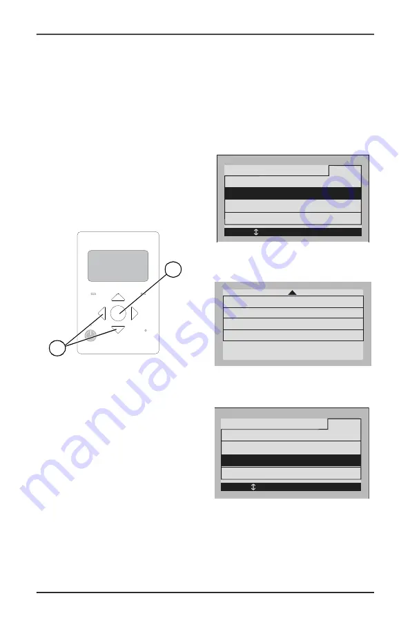
Figure 6-1. Inverter Control Panel
Commissioning the Rebus
System
The PV Link ships from the factory in a dis
-
abled state. Each unit must be enabled from
the PWRcell inverter control panel. Once
enabled, the PV Link automatically detects the
REbus nanogrid and begins to export power
when the bus is within normal operating speci
-
fications.
See the Generac PWRcell Inverter Installation
Manual for instructions on commissioning the
REbus system.
PVRSS Commissioning with
SnapRS Devices
To enable PV Link to work as a PVRSS with
SnapRS devices:
1.
Press the right arrow button on the control
panel repeatedly until the device page
appears.
NOTE:
The device page display should read
Disabled. If it does not read Disabled, press
the center button and disable the device.
2.
See
.
Press the center button
and select Mod. Settings to access device
settings and options.
3.
and SnapRS Important Information
, found
on the front cover of this manual.
Figure 6-2. PVRSS Commissioning (1 of 4)
4. See
. If installing a dual string
array, select Mod. Settings and update the
String Count value to 2.
Figure 6-3. PVRSS Commissioning (2 of 4)
5. See
. Press the center button
and select Enable w/PVRSS to enter the
Testing PVRSS state.
Figure 6-4. PVRSS Commissioning (3 of 4)
REbus
Inverter
Internet
Shutdown
(hold)
009894
B
A
Disable
PV Link S2502
Menu
Mod. Settings
Enable w/PVRSS
RCPn: 00010003XXXX
< EXIT SCROLL > NEXT • SELECT
PLM Channel:
Vin Startup:
String Count:
Cancel
Commit
off
120.0V
2
Enable PVRSS:
1
Disable
PV Link S2502
Menu
Mod. Setting
s
RCPn: 00010003XXXX
< EXIT SCROLL > NEXT • SELECT
Enable w/PVRSS
Summary of Contents for PV Link
Page 7: ...4 Installation Manual for PV Link and SnapRS This page is intentionally left blank...
Page 13: ...10 Installation Manual for PV Link and SnapRS This page is intentionally left blank...
Page 15: ...12 Installation Manual for PV Link and SnapRS This page is intentionally left blank...
Page 23: ...20 Installation Manual for PV Link and SnapRS This page is intentionally left blank...
Page 25: ...22 Installation Manual for PV Link and SnapRS This page is intentionally left blank...
Page 27: ...24 Installation Manual for PV Link and SnapRS This page is intentionally left blank...


