16
Owner’s Manual for Mobile Light Tower
Operation
Figure 3-5. Crank Engine
4.
See
. Release the key, it will move to the
RUN position.
Figure 3-6. Release Key
5.
Once the engine is running, allow it to reach
normal operating temperature before switching on
any loads.
Automatic Shutdown
This unit is equipped with a low oil pressure and high
coolant temperature automatic shutdown system. This
system will automatically shut off the fuel supply to stop
the engine if oil pressure drops too low or the engine
exceeds normal operating temperature. Return the main
circuit breaker to the OFF (O) position to reset the unit
after the cause of shutdown has been determined.
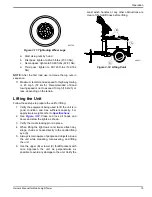
Light Operation
1.
Verify the unit is on and running smoothly.
2.
. Switch the main circuit breaker (A)
ON (I).
3.
Switch the individual circuit breakers for the lights
(B) to the ON (I) position, one at a time.
4.
The ballast indicator lights (C) will turn on and
continue to get brighter as the lights warm up, and
then remain on. This confirms power is coming
from the ballasts to the lights.
Figure 3-7. Light Switches and Breaker
NOTE:
If an indicator light does not turn on, see
or contact a GMASD.
NOTE:
The lights require a warm up period of 5-15
minutes before they reach full output. If the lights are shut
down, they require a cool down period of approximately
ten minutes before they can be switched on again.
NOTE:
The light tower uses four 1100W bulbs. When
checking or replacing the bulbs, wipe them with a clean
cloth to avoid leaving any grease, oil residue or
fingerprints on the glass. Any residue can create a hot
spot on the bulb, causing premature bulb failure.
Voltage Regulator (If Equipped)
Some units may be equipped with an electronic voltage
regulator. The voltage regulator controls the output of the
generator by regulating the current into the exciter field.
The voltage regulator is adjusted before shipment from
GLOW
PLUG
OFF
RUN
START
003793
GLOW
PLUG
OFF
RUN
START
003794
(000277)
WARNING
Burn hazard. Never operate lights with a
damaged or missing lens cover. Lamps are
hot and pressurized while in use. Unprotected
lamps can shatter, causing severe injury.
400W
400W
Flagger Station Switches
120V
240V
DC
BREAKER
TURN
MAIN
BREAKER
OFF
120V
BREAKER
MAIN
BREAKER
240V
BALLAST INDICATOR LIGHTS
MAST LIGHT SWITCHES
I
O
I
O
I
O
I
O
NEUTRAL BONDED TO FRAME
ON
ON
ON
ON
ON
ON
GLOW PLUG
INDICATOR
OFF
RUN
START
GLOW
PLUG
A
B
C
(000278)
WARNING
Burn hazard. Lamps become extremely hot
while in use. Allow 10–15 minutes for cooling
before handling or lowering mast. Touching a
hot lens or fixture can cause severe burns.
Summary of Contents for MLT4060KV
Page 4: ...iv Owner s Manual for Mobile Light Tower Trailer Lights Wiring 33 ...
Page 24: ...20 Owner s Manual for Mobile Light Tower Operation This page intentionally left blank ...
Page 35: ...Owner s Manual for Mobile Light Tower 31 Wiring Diagrams DC Wiring Electric Winch ...
Page 36: ...32 Owner s Manual for Mobile Light Tower Wiring Diagrams DC Wiring for Optional Equipment ...
Page 38: ...34 Owner s Manual for Mobile Light Tower Wiring Diagrams This page intentionally left blank ...
Page 39: ......


