background image

General Information and Setup

Owner’s/Installation Manual for SMM

5

Setting Lockout

SMMs are equipped with a lockout provision. The SMM
can be set to enable LOCKOUT mode if load is identified
as non-essential and does NOT need to operate on
backup power during generator overload. Load can be a
single electrical load or an entire subpanel of multiple
branch circuits.

NOTE: 

LOCKOUT mode works in an overload condition,

which is determined by generator frequency. If generator
has sufficient capacity, the load will be allowed to turn on
even if control is set to LOCKOUT mode.

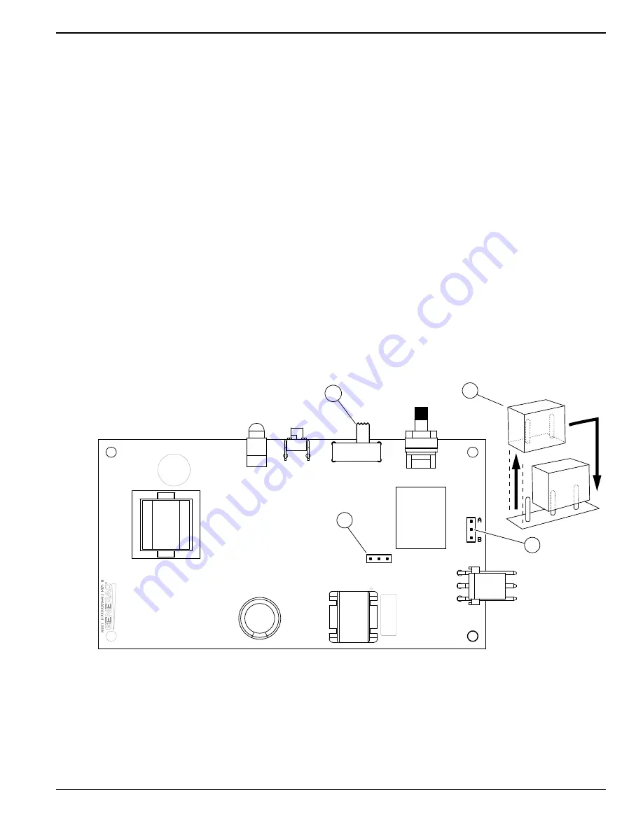
See 

Figure 2-2

. To set SMM to enable standard lockout

mode, slide lockout switch (1) to LOCKOUT LOAD ON
GENERATOR.

Jumper Locations

See 

Figure 2-2

. The SMM control board is equipped with

two movable jumpers (2). Jumper locations are indicated
on the diagram:

(3) Frequency Jumper - default for 60 Hz

(4) Mode Selector Jumper (identified on control
board as “Lock Out Jumper”) - position A is default
for most applications

NOTE: 

Change in jumper (4) is only required for specific

applications and should not be moved under normal cir-
cumstances. If unit is installed in an area with unstable
frequency power, change the lockout jumper (4) to posi-
tion B.

IMPORTANT NOTE: Jumper (3) should remain in
place unless in an area with 50 Hz power.

To move a jumper:

1.

Remove power.

2.

Grasp jumper and pull straight up until it clears the
pins. 

3.

Move jumper to new location and press it gently
onto the pins until seated.

NOTE: 

To avoid bending or breaking pins, do not rock

jumper, use excessive force, or pull sideways to remove
it from the SMM control board.

Figure 2-2.  Jumper Locations

J1

SW3

SW1

LED

L1

J2

50Hz 60Hz

JUMPER

LOCK OUT

JUMPER

C12

C4

007115

3

4

2

1

Summary of Contents for G007000-0

Page 1: ...RAC COM 1 888 GENERAC 1 888 436 3722 Para espa ol visita http www generac com service support product support lookup Pour le fran ais visiter http www generac com service support product support looku...

Page 2: ...ii Owner s Installation Manual for SMM 000393a WARNING CANCER AND REPRODUCTIVE HARM www P65Warnings ca gov...

Page 3: ...ation Considerations 3 Smart Management Module SMM 3 SMM and Carton Contents 4 Setting Lockout 5 Jumper Locations 5 Section 3 Installation Tests Troubleshooting Electrical Specifications 9 Enclosure S...

Page 4: ...Table of Contents iv Owner s Installation Manual for SMM This page intentionally left blank...

Page 5: ...es The manufacturer cannot anticipate every possible cir cumstance that might involve a hazard The alerts in this manual and on tags and decals affixed to the unit are not all inclusive If using a pro...

Page 6: ...Introduction and Safety 2 Owner s Installation Manual for SMM This page intentionally left blank...

Page 7: ...e SACM as the top priorities then use additional SMMs as the remaining priorities To reduce the loads returned to the generator all at once it is best to set the SMM priorities to follow after the las...

Page 8: ...sitions are LOCKOUT LOAD ON GENER ATOR enabled and LOCKOUT DISABLED See Table 2 2 NOTE Recovery time is based on priority dial settings See Table 2 1 Test Button C Disables contactor output for a spec...

Page 9: ...ped with two movable jumpers 2 Jumper locations are indicated on the diagram 3 Frequency Jumper default for 60 Hz 4 Mode Selector Jumper identified on control board as Lock Out Jumper position A is de...

Page 10: ...erator mode or during a first time utility power up for five minutes of initial operation Lockout 30 minutes 3 second flash 3 On 3 Off Generator Module detected an overload while trying to recover fro...

Page 11: ...the l oad Module now in lockout recovery NO YES Have load shed recovery time a nd module priority time elapsed 1 YES NO Was lockout recovery operation successful YES NO YES NO Notes 1 Refer to the Pr...

Page 12: ...General Information and Setup 8 Owner s Installation Manual for SMM This page intentionally left blank...

Page 13: ...ditional information Mounting Instructions Recommended installation is near the electrical panel or appliance load The enclosure has a NEMA 3R rating and can be mounted indoors or outdoors It provides...

Page 14: ...rce and load lines to transfer switch and SMM NOTE Suitable conduit fittings must be installed in knockout openings when running supply and load wires Height in mm H1 6 17 156 8 H2 2 36 60 Width in mm...

Page 15: ...ntil power returns during an outage Delay time for post load shed recovery An example configuration is shown below Configurations will vary depending on customer prioritization of loads 1 Set the prio...

Page 16: ...time delay see Table 2 1 for unit to enable output Load not powered LED flashing 3 second interval This load overloaded the generator while attempting recovery from a shed It is in a 30 minute lockou...

Page 17: ...Installation Tests Troubleshooting Owner s Installation Manual for SMM 13 This page intentionally left blank...

Page 18: ...Installation Tests Troubleshooting 14 Owner s Installation Manual for SMM This page intentionally left blank...

Page 19: ......

Page 20: ...rights reserved Specifications are subject to change without notice No reproduction allowed in any form without prior written consent from Generac Power Systems Inc Generac Power Systems Inc S45 W2929...

Reviews: