Generac Power Systems 00940-2, Owner'S Manual And Installation Instructions
The Generac Power Systems 00940-2 is an exceptional power generator designed for reliable and uninterrupted power supply. To assist you in safely installing and operating this device, we offer the Owner's Manual and Installation Instructions. Download this manual for free from our website and ensure hassle-free usage of your Generac power generator.
Share
Download


Reviews:
No comments
Related manuals for 00940-2
MP301
Brand: CA Pages: 6

FG1600i-A
Brand: Feider Machines Pages: 36

P03619
Brand: Firman Pages: 51

SDV685-AC
Brand: NextBase Pages: 54

Yakumo DVD Travelle
Brand: YAKUMO Pages: 40

MES-404
Brand: LENCO Pages: 52

TF-DVD5007
Brand: Coby Pages: 1

GA-9.7HE
Brand: MULTIQUIP Pages: 88

SPG 1000
Brand: Tektronix Pages: 282

GV-3000
Brand: Koshin Pages: 36

FX POWER SOURCE 12
Brand: Accel Pages: 11

DVD8039B
Brand: Curtis Pages: 5

XTL-W70
Brand: Sony Pages: 4

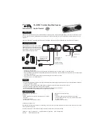
Watchman FDL-250T
Brand: Sony Pages: 20
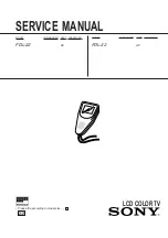
Watchman FDL-22
Brand: Sony Pages: 21

XTL-6100MK2
Brand: Sony Pages: 40

XTL-W70
Brand: Sony Pages: 48

XTL-W70
Brand: Sony Pages: 84


