background image

3

www.remotepossibilities.com

„


Enabling the Backup Battery

Attach the shorting clip (included with the unit) between the “BATT OUT” and “DC IN” terminals. If the
shorting clip is lost, a short length of wire can be used. Once enabled, the battery will require up to 24 hours to
fully charge.

„


Disabling the Backup Battery

To disable the backup battery, remove the shorting clip from between the “BATT OUT” and “DC IN”
terminals.

„


Testing the Backup Battery

When operating from AC power, the power light on the front panel of the Messenger 570 system is green.
When operating from battery, the power light is red.

Test the battery at least once per year by removing the Messenger 570’s AC power source for 10 to 15 minutes
and verifying that the power light changes to red and that the unit responds to an incoming phone call.

Attaching the Inputs

The Messenger 570 system supports eight universal inputs that can accept a variety of input types. Input expansion
modules are available to increase the monitoring capability of the Messenger 570 to 32 inputs (see Input Expansion
Modules).

Inputs 1 through 4 are factory pre-configured to accept 4-20 mA signals while inputs 5 through 8 are factory pre-
configured to accept dry-contact signals.  It is easy to re-configure an input to accept 4-20 mA, 0-5 VDC,
thermistor, logic-level, dry-contact or other signal types in any combination.

„


DIP Switch Settings 

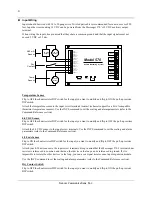
Removing the input connector reveals two banks of DIP switches as illustrated in the figure below. Each bank
has eight switches labeled 1 through 8 corresponding to inputs 1 through 8. The upper bank controls 200-ohm
shunt resistors (required for current monitoring applications) while the bottom bank controls pull-up resistors
(required for temperature monitoring and dry-contact applications.

12

345678

12345678

Input 1

Common

Input 2

Common

Input 3

Common

Input 4

Common

Input 5

Common

Input 6

Common

Input 8

Common

Input 7

Common

Shunt Resistors

Pull-Up Resistors

OFF              ON

Summary of Contents for Messenger 570

Page 1: ...i i November 2001 Messenger 570 Remote Monitoring System USER S GUIDE It s never been so easy fast or inexpensive to monitor remote sites ...

Page 2: ...rt telemetry unit This User s Guide outlines the handful of easy straightforward steps you need to take to prepare the Messenger 570 system for its monitoring alarm control and other assignments We are committed to helping you realize the remote possibilities If there is a question that cannot be answered quickly and completely in our documentation please call our Technical Support Hotline 1 800 2...

Page 3: ...ting the Backup Battery 3 Attaching the Inputs 3 DIP Switch Settings 3 Input Wiring 4 Input Expansion Modules 5 Connecting the Outputs 5 Output Relays 5 Switched AC Outlet 6 Communications 7 Using a Phone Line 7 Voice Mode 7 Modem Mode 8 Fax Mode 9 Internet Access 9 Using the RS 232 Port 9 Commissioning Checklist 10 Identify the System 10 Configure the Inputs 10 Configure the Data Logger 10 Config...

Page 4: ...de Reporting 21 Custom Voice Phrases 21 Custom Greeting 22 Command Reference 23 ALM Alarm Commands 23 Help with the ALM command 23 Alarm Reports 23 Alarm Set up 24 BYE End Session 25 COM Communications Gateway 25 Help with the COM command 25 Open Communications Gateway 25 Communications Gateway Set up 26 CNT Pulse Counter 28 Help with the CNT command 28 Counter Report 28 Clear Counters 29 CRT S Cr...

Page 5: ...ith the POW Command 55 Power Status Report 55 Power Failure Alarm Parameters 55 RTU Real Time Update 56 RTU 56 RUN Runtime Meters 56 Help with the RUN command 56 Runtime Meter Report 57 Resetting the Runtime Meters 57 SCH Scheduled Dialout 57 Help with the SCH Command 57 Scheduled Dialout Settings 58 SEC Security Identification 58 Help with the SEC command 58 Security Report 59 Add Edit Security C...

Page 6: ...wer Inlet Switched AC Outlet Battery Disconnect DC Output Power Indicator Alarm Indicator A home for your Messenger 570 Your new Messenger 570 should be located in a convenient location close to the conditions being monitored in a warehouse basement utility closet or other work area mounted on a wall or mounted inside an equipment cabinet When mounted in an optional NEMA 4X weatherproof enclosure ...

Page 7: ...ctrical outlet The power required by the Messenger 570 is 20 watts plus the wattage of the load if any attached to the AC Switched Output connector DC Operation Connect the positive lead of a 9 to 15 VDC source to the DC IN terminal and connect the negative lead to the Common terminal IMPORTANT When using DC power the Messenger 570 s AC power cord MUST be disconnected AND its backup battery MUST b...

Page 8: ...uts that can accept a variety of input types Input expansion modules are available to increase the monitoring capability of the Messenger 570 to 32 inputs see Input Expansion Modules Inputs 1 through 4 are factory pre configured to accept 4 20 mA signals while inputs 5 through 8 are factory pre configured to accept dry contact signals It is easy to re configure an input to accept 4 20 mA 0 5 VDC t...

Page 9: ... of compatible thermistor temperature sensors Use the INP S command to set the scaling and alarm parameters refer to the Command Reference section 0 5 VDC Sensor Flip to OFF the shunt resistor DIP switch for the input you want to modify and flip to OFF the pull up resistor DIP switch Attach the 0 5 VDC sensor to the input screw terminals Use the INP S command to set the scaling and alarm parameter...

Page 10: ...h Wire the 110 220 VAC signal to the coil of a suitably rated relay Wire the relay contacts to the input screw terminals Use the INP S command to configure the input for a dry contact sensor refer to the Command Reference section Other To connect a thermocouple millivolt or other type sensor to the Messenger 570 use an appropriate signal conditioner Contact technical support for assistance Input E...

Page 11: ...itched AC Outlet You can also plug equipment seven amp maximum load into the Switched AC power outlet located on the side of the unit 110 VAC units only This switched outlet works in unison with the output 1 relay on the front panel ...

Page 12: ...stent voice without the need for set up programming or recording The Messenger 570 can also be programmed to call a facsimile machine at predetermined times and deliver a concise status report IMPORTANT Information intended exclusively for voice mode users is highlighted in this guide by a telephone icon and use of this different type face Voice Mode The Messenger 570 will respond to your call by ...

Page 13: ...ction Defining a HyperTerminal Connection To use HyperTerminal you must first define a few parameters including the phone number of the Messenger 570 To start HyperTerminal click Start and then click Programs Accessories and Hyperterminal Look for an icon labeled HyperTerminal or Hypertrm exe and click on it In the Connect Description box type a name for the connection choose an icon then click OK...

Page 14: ...he following sections of this manual are step by step procedures that will help you prepare the Messenger 570 system to work for you describing how to designate individuals you want to receive alarm messages set low and high alarm set points etc The commands to access the system are simple three letter codes e g INP input ALM alarm PHO telephone generally followed by a fourth letter e g R report S...

Page 15: ... several programmable fields to help identify it in both voice and data modes These fields include site name and code number for data mode identification and unit phone number for voice mode identification The information that you enter in these fields will not affect the operation of the unit but will help you manage information from your remote sites Use the SEC S command to enter system identif...

Page 16: ...It will send the message to up to eight designated telephone numbers anywhere on or off site and at any time If the calls are unanswered the Messenger 570 system will wait a pre set length of time and perform the complete dial out sequence again The alarm dial out sequence will continue even if the alarm condition has cleared until the alarm has been externally acknowledged To fully configure the ...

Page 17: ...of the eight inputs including any that may have exceeded an alarm set point type INP R at the command prompt Analog inputs will provide LO HI and OK status discrete will provide AL and OK indicators COMMAND INP R INPUT STATUS REPORT Outside Air OK 82 F Input 2 OK 66 F Input 3 OK 83 F Input 4 OK 85 F Input 5 OK 85 F Input 6 OK 85 F Input 7 OK 85 F Input 8 OK 85 F Time 08 03 96 11 12 36 Output Repor...

Page 18: ...ted dial out phone names and numbers type PHO R at the command prompt COMMAND PHO R PHONE NUMBER REPORT 1 Phone 1 No Number 2 Phone 2 No Number 3 Phone 3 No Number 4 Phone 4 No Number 5 Phone 5 No Number 6 Phone 6 No Number 7 Phone 7 No Number 8 Phone 8 No Number Security Report To get a report of various system counters and timers type SEC R at the command prompt Note These counters and timers ar...

Page 19: ...knowledged alarms Any alarms which have not been acknowledged An unacknowledged alarm initiates an alarm dial out sequence Alarm Dial Out Reminder An optional feature of the Messenger 570 system will enable the dial out sequence even after an alarm has been acknowledged When an alarm occurs the Messenger 570 system will dial out to all phone numbers in its phone number list once or until it is ack...

Page 20: ...wledged in either data or voice mode To acknowledge an alarm and prevent the Messenger 570 system from dialing out again until new alarm conditions exist type ALM Responding to an Alarm Message Data Mode local For local response an indicator on the front panel of the Messenger 570 system will flash if there are any unacknowledged alarms An ALARM CANCEL switch enables alarms to be canceled from the...

Page 21: ...settings among the four output channels The output control mode settings can be found in the OUT S menu AVAILABLE CHOICES 1 Manual 2 Automatic 3 Automatic Day 4 Automatic Night 5 Close on Present Alarms 6 Open on Present Alarms 7 Close on Unacknowledged Alarms Manual Manual control permits an operator to remotely control the on off state of the four output relays Use the OUT O command and select t...

Page 22: ...sk correlates to input 1 the most significant bit of the mask correlates to input 8 If a bit in the mask is set to 0 alarms on the correlating input will not control the output Conversely if a bit is set to 1 an alarm on the correlating input will control the output As an example if you want output 1 to be controlled by alarms on input channels 1 through 4 but ignore alarms on channels 5 through 8...

Page 23: ...ctions and to set up log time type LOG S COMMAND LOG S DATA LOG SETUP 1 Periodic Log Enable Disabled 2 Periodic Log Rate 00 01 00 0 hh mm ss 3 High Resolution Log Enabled 4 Clear Periodic Log 0 Previous Menu Choose a Number Periodic Recording To enable or disable the periodic recording of all input and output conditions type LOG S and choose 1 When turned on the Messenger 570 system will automatic...

Page 24: ...Display data log configuration 0 Previous Menu Choose a Number Uncompressed Log Format All uncompressed records contain comma delimited ASCII fields The following format is used for all uncompressed records received from the data logger REC MM DD YY hh mm ss s Reserved XIN A1 A2 A3 A4 A5 A6 A7 A8 O1 O2 O3 O4 O5 O6 O7 O8 REC Record type MM DD YY Month Date Year hh mm ss s Hour Minute Second Reserve...

Page 25: ...ressed logs Downloading a compressed log file is also possible The data compression scheme used in the Messenger 570 system strips out all commas and other punctuation and converts the data from ASCII decimal to binary The result is a data file which is at least one fourth its original size and transfers in one fourth the time of the original data file To decompress the data to its original comma ...

Page 26: ...e session Creating these voice files and uploading them is a three step process 1 RECORD Each voice phrase is recorded as an individual WAV file on your PC The WAV must be in a PCM format at 22 050 Hz with 16 bit mono samples Once you have recorded your phrases you need to make sure that they are not longer than the maximum time period allowed 8 88 seconds for the greeting and 1 11 seconds for all...

Page 27: ...hat file needs to be uploaded All of the custom phrases and voice files are stored in non volatile memory and are not affected by a power outage They are however erased when performing a flash code update Custom Greeting The 17th phrase is a custom greeting that is played at the beginning of a voice mode session This message replaces the Hello this is telephone number that is played as the default...

Page 28: ...m to continually monitors all inputs for alarm conditions If a set point has been exceeded for a designated period of response time the Messenger 570 system recognizes this as the existence of an alarm condition Help with the ALM command Type ALM at the command prompt and the Messenger 570 system will return a list of valid alarm commands and related instructions COMMAND ALM ALARM FUNCTIONS ALM R ...

Page 29: ...nternal beeper will sound whenever an unacknowledged alarm exists When disabled the beeper will never sound COMMAND ALM S ALARM SETUP 1 Local Alarm Siren Enabled 2 Dial out Interval 60 min 3 Dial out Delay 1 min 0 Previous Menu Choose a Number 1 Local Alarm Siren Enabled Change Present State y n No Dial out Interval This parameter specifies the amount of time the Messenger 570 system will wait aft...

Page 30: ...be used to establish communications with a secondary Messenger 570 system or almost any other device that has an RS 232 port When using the communications gateway make sure that the RS 232 cable connecting the Messenger 570 system and secondary device supports full hardware RTS CTS handshaking If the secondary device does not support hardware handshaking you must make sure that neither device tran...

Page 31: ...onds of silence will close gateway Communications Gateway Set up Type COM S at the command prompt and the Messenger 570 system will display a sub menu of related parameters that you can alter COMMAND COM S COMMUNICATIONS SETUP 1 Local RS 232 Baud Rate 38 4k 2 Smart Gateway Mode Disabled 3 Gateway Echo Disabled 0 Previous Menu Local RS 232 Baud Rate The baud rate can range from 4 8 to 115 6 kbps ...

Page 32: ...rt Gateway Mode When Smart Gateway Mode is enabled the Messenger 570 system s serial port will remain inactive until it sees a CONTROL A COMMAND COM S COMMUNICATIONS SETUP 1 Local RS 232 Baud Rate 38 4k 2 Smart Gateway Mode Enabled 3 Gateway Echo Disabled 0 Previous Menu Choose a Number 2 Smart Gateway Mode Enabled Change Present State y n Yes Gateway Echo When enabled characters that are received...

Page 33: ...cond with no two transitions occurring within less than 10ms of each other The signal can be a square saw tooth or sine wave with a transition being a change from above three volts and below two volts and vice versa Total counts are displayed as decimals Help with the CNT command Type CNT at the command prompt and the Messenger 570 system will return a list of valid counter commands and related in...

Page 34: ... 03 Critical 19 Input 19 Non critical 04 Input 04 Critical 20 Input 20 Non critical 05 Input 05 Non critical 21 Input 21 Non critical 06 Input 06 Non critical 22 Input 22 Non critical 07 Input 07 Non critical 23 Input 23 Non critical 08 Input 08 Non critical 24 Input 24 Non critical 09 Input 09 Critical 25 Input 25 Non critical 10 Input 10 Critical 26 Input 26 Non critical 11 Input 11 Critical 27 ...

Page 35: ...Critical Input Channels 2 Set Check Critical Condition Threshold 3 Set Check Critical Condition Actions 0 Previous Menu Choose a Number 3 SET CHECK CRITICAL CONDITION ACTIONS 1 Freeze Secondary Logger Disabled 0 Previous Menu CRT R Critical Condition Report COMMAND CRT R CRITICAL CONDITION REPORT Critical Condition Status No critical condition exists An active critical condition exists An inactive...

Page 36: ...nually resets the critical condition logic using the CRT O command COMMAND CRT O CRITICAL CONDITION OPERATIONS No critical condition exists There are n critical input channels currently in the active alarm state which does not meet or exceed the critical condition threshold of n channels COMMAND CRT O CRITICAL CONDITION OPERATIONS An inactive critical condition exists Resetting the critical condit...

Page 37: ...IP switch settings for the unit s current input setup Note This report does not indicate the current DIP switch settings It only reports how the DIP switches should be set COMMAND DIP R TOP DIP SWITCH 0 OFF 1 OFF 2 OFF 3 OFF 4 ON 5 ON 6 ON 7 ON BOTTOM DIP SWITCH 0 ON 1 ON 2 ON 3 ON 4 OFF 5 OFF 6 OFF 7 OFF The example above shows what a report would look like if you had inputs 1 4 defined as 4 20 m...

Page 38: ...means of Look Up tables Each input has separate alarm and control set points The control set points can be used to automatically control output devices see OUT S Help with the INP command Type INP at the command prompt and the Messenger 570 system will return a list of valid input commands and related instructions COMMAND INP INPUT FUNCTIONS INP R Input Status Report INP S Set Check Input Settings...

Page 39: ...nput Damping Input damping causes the Messenger 570 to react slowly to a rapidly changing input For example if temperature were being monitored and the temperature probe was moved from an ice bath to a hot water bath a damped input would show a gradual change in temperature every 10 to 20 seconds rather than an instantaneous change This option will eliminate many false alarm situations COMMAND INP...

Page 40: ...nput Setup Parameters Type INP S at the command prompt to control the configuration parameters for each input You will get a list of all configurable inputs Select the input you wish to configure and you will get a sub menu containing parameters for that input COMMAND INP S SET CHECK INPUT SETTINGS 1 Input 1 Label 2 Input 2 Label 3 Input 3 Label 4 Input 4 Label 5 Input 5 Label 6 Input 6 Label 7 In...

Page 41: ...mperature C x x x Dry Contact x x x Pulse Totalizer x x x Pulse Rate x x x Linear x x x 4 to 20 mA x x x Extended Input X X Alarm Parameters High Alarm Setpoint Low Alarm Setpoint Alarm State Respons e Time Rate Setpoint Temperature F x x x x Temperature C x x x x Dry Contact x x Pulse Totalizer x x Pulse Rate x x x Linear x x x x 4 to 20 Ma x x x x Extended Input X X X Output Control Parameters O...

Page 42: ... eight input channels can be given a name Type INP S and choose from the menu the input you want to name A second menu will be given listing all parameters associated with that input Choose menu item 1 Label and enter the label name for the input At the enter label prompt accepts 1 to 12 characters accepts all data characters A Z a z 0 9 specials pressing ENTER without entering any characters keep...

Page 43: ...abel 8 Input 8 Label 0 Previous Menu Choose a Number 1 Input 1 PRESENT SETTINGS 01 Label Label 02 Sensor Type Temperature F 03 High Alarm Set Point 260 04 Low Alarm Set Point 94 05 Response Time 0 Sec 06 Output On Set Point 260 07 Output Off Set Point 94 08 Calibration Offset 0 09 Data Logging Enabled 00 Previous Menu Choose a Number 1 Enter New Label Outside Air Sensor Type ...

Page 44: ...Dry Contact 4 Pulse Totalizer 5 Pulse Rate 6 Linear 7 Reserved Custom A 8 Reserved Custom B 9 4 to 20mA 0 Previous Menu Choose a Number 6 Alarm Set Points Each of the input channels can be given alarm set points Inputs configured with a temperature pulse rate custom linear or 4 to 20 mA sensor type can be given high and low alarm set points Inputs configured as pulse totalizers have only a high al...

Page 45: ...nput 6 Label 7 Input 7 Label 8 Input 8 Label 0 Previous Menu Choose a Number 1 Input 1 PRESENT SETTINGS 01 Label Outside Air 02 Sensor Type Temperature F 03 High Alarm Set Point 260 04 Low Alarm Set Point 94 05 Response Time 0 Sec 06 Rate Alarming Disabled 07 Output On Set Point 260 08 Output Off Set Point 94 09 Calibration Offset 0 10 Data Logging Enabled 00 Previous Menu Choose a Number 3 Enter ...

Page 46: ... the high and low set points which are continuously scanned 10 times second the rate at which these inputs are scanned for rate of change condition is based on the rate of change scan period See INP O The rate of change scan period is a global user programmable time period from 1 second to 24 hours Being global this period applies to all temperature linear and 4 20 ma sensor types Upon system rese...

Page 47: ...8 Label 0 Previous Menu Choose a Number 1 Input 1 PRESENT SETTINGS 01 Label Outside Air 02 Sensor Type Temperature F 03 High Alarm Set Point 260 04 Low Alarm Set Point 94 05 Response Time 120 Sec 06 Rate Alarming Disabled 07 Output On Set Point 260 08 Output Off Set Point 94 09 Calibration Offset 0 10 Data Logging Enabled 00 Previous Menu Choose a Number 7 Enter New Output On 255 Calibration Each ...

Page 48: ...SENT SETTINGS 01 Label Outside Air 02 Sensor Type Temperature F 03 High Alarm Set Point 260 04 Low Alarm Set Point 94 05 Response Time 120 Sec 06 Rate Alarming Disabled 07 Output On Set Point 260 08 Output Off Set Point 94 09 Calibration Offset 0 10 Data Logging Enabled 00 Previous Menu Choose a Number 8 Sensor Calibration Outside Air OK 84 F Enter current sensor value 82 Data Logging Data logging...

Page 49: ... On Set Point 255 07 Output Off Set Point 94 08 Calibration Offset 2 09 Data Logging Enabled 00 Previous Menu Choose a Number 9 Warning Changing this option will reformat the data logs permanently erasing all log data Data Logging for this input is Enabled Change Present State y n No Dry Contact Specific Parameters Input 1 PRESENT SETTINGS 01 Label Input 1 02 Sensor Type Dry Contact 03 Open Descri...

Page 50: ...ounter These 24bit counts can be viewed with the CNT R command If you want to log or alarm on an input s pulse count total you must set that input s sensor type to Pulse Totalizer If you want to log or alarm on an input s hourly pulse rate then you must set that input s sensor type to Pulse Rate When using either of these types only the 16 least significant bits are used This provides a count or h...

Page 51: ...G O DATALOG OPERATIONS 1 Download uncompressed periodic log in ASCII 2 Download uncompressed periodic log using X modem 3 Download compressed periodic log using X modem 4 Display data log configuration 0 Previous Menu Choose a Number Download Uncompressed ASCII Information downloaded in this format can be read directly on the screen The uncompressed ASCII log download option causes the Messenger 5...

Page 52: ...oad uncompressed periodic log using X modem 3 Download compressed periodic log using X modem 5 Display data log configuration 0 Previous Menu Choose a Number 5 Current Data Log Configuration Input 1 Logging Input 2 Logging Input 3 Logging Input 4 Logging Input 5 Logging Input 6 Logging Input 7 Logging Input 8 Logging Periodic log capacity 1364 records Current log usage 7 77 Configure the Data Logg...

Page 53: ... erases the contents of the data logger s memory Note you normally do not have to clear memory when it is full it will automatically clear the oldest information in its memory You can use this clear function after you download the contents of the data logger s memory if you want to eliminate the possibility of downloading redundant information in the future OUT Output Commands The Messenger 570 sy...

Page 54: ...ng the space bar Press ENTER when the output is in the desired state The Messenger 570 system will repeat the process with the next output and continue doing so until all of the outputs have been accessed COMMAND OUT O TURN OUTPUTS ON OR OFF Press SPACE to change CR if OK Output 1 OFF ON OFF Output 2 OFF ON Output 3 OFF ON Output 4 OFF ON Output Setup Type OUT S at the command prompt to control th...

Page 55: ...and choose from the menu the input you want to name A second menu will be given listing all parameters associated with that input Choose menu item 1 Label and enter the label name for the input Each label can be up to 12 characters long and can contain any alphanumeric or printable character Hiding Outputs By typing HIDE you are able to remove this particular item from all reports To bring the inp...

Page 56: ...n the output will cycle on for 40 seconds and off for 20 seconds ad infinitum If the parameter is set for 60 the output remains on constantly The minimum value is one The default value is 60 seconds COMMAND OUT S SET CHECK OUTPUT SETTINGS 1 Output 1 Heater 2 Output 2 Label 3 Output 3 Label 4 Output 4 Label 0 Previous Menu Choose a Number 1 Output 1 PRESENT SETTINGS 1 Label Label 2 On Time per Minu...

Page 57: ...tic 3 Automatic Day 4 Automatic Night 5 Close on Present Alarms 6 Open on Present Alarms 7 Close on Unacknowledged Alarms 0 Previous Menu Choose a Number 2 Power up State By default all outputs are off after a power up reset By changing the Power up State setting to On you can have an output turn on immediately after a reset Alarm Mask See Controlling Outputs for description of control modes PHO T...

Page 58: ...ory Phone Directory Listing This lists the names phone numbers and dialing instruction that have been programmed into the Messenger 570 s memory COMMAND PHO R PHONE NUMBER REPORT 1 J Flynn F5432151 2 Data Ctr V1 215 543 8066 68 3 Phone 3 No Number 4 Phone 4 No Number 5 Phone 5 No Number 6 Phone 6 No Number 7 Phone 7 No Number 8 Phone 8 No Number Add Edit Phone Numbers This enables you to change th...

Page 59: ...3 Erase Entry 0 Previous Menu Choose a Number 1 Enter New Label J Smith OK Entry Updated 1 J Smith F5432151 1 Change Label Name 2 Change Phone Number 3 Erase Entry 0 Previous Menu Choose a Number 2 When entering a phone number the first character is used to determine the type of dial out Valid choices are V Voice Mode D Data Mode F Fax Mode This prefix is not optional Enter New Phone Number V555 1...

Page 60: ...AC Power Monitor Help with the POW Command Type POW at the command prompt and the Messenger 570 system will return a list of valid power monitoring commands and related instructions COMMAND POW AC POWER FUNCTIONS POW R AC Power Report POW S Set Check AC Power Fail Settings Power Status Report This enables you to report the current condition of the AC line power that is supplying operating voltage ...

Page 61: ...ages Enter a much smaller time if you are monitoring power sensitive devices but set it much higher if the location is prone to long power outages and the equipment you are monitoring would not be affected RTU Real Time Update RTU Type RTU at the command prompt and the Messenger 570 system will return a continuously updated input output status report RUN Runtime Meters An input s runtime meter is ...

Page 62: ...ype RUN O at the command prompt to reset any or all of the runtime meters COMMAND RUN O INPUT RUNTIME OPERATIONS 1 Clear Outside Air 00 00 2 Clear Input 2 00 00 3 Clear Input 3 00 00 4 Clear Input 4 00 00 5 Clear Input 5 00 00 6 Clear Input 6 00 00 7 Clear Input 7 00 00 8 Clear Input 8 00 00 9 Clear all input runtimes 0 Previous Menu Choose a Number SCH Scheduled Dialout Help with the SCH Command ...

Page 63: ...y Delivery Day If the scheduler interval is set to weekly you can select what day of the week you wish the Messenger 570 system to dial out Delivery Hour This defines what hour the Messenger 570 system will dial out Phone Number This is the phone number the Messenger 570 system will call and deliver its status reports to Call type can be either voice data or fax See PHO O for a description of how ...

Page 64: ...ation fields that are used to safeguard the Messenger 570 system s data and authenticate the location of the site originating the data Several of these fields are user programmable and can be changed by typing SEC S at the command prompt COMMAND SEC S SET CHECK SECURITY SETTINGS 1 Security Code 1 2 Security Code 2 3 Security Code 3 4 Code Number 5 Unit Phone Number 6 Site Name 7 Automatic Report D...

Page 65: ...ic Report Disabled 0 Previous Menu Choose a Number 1 Enter New Level 1 Security Code To avoid misspelling errors Enter New Level 1 Security Code Security Code 1 updated Entering your code number You can program an eight character alphanumeric code to provide your Messenger 570 system a unique identity That code which will appear in the log on message typically is an account number site code or ser...

Page 66: ...system will run a self diagnostic test and generate a report COMMAND TST R SYSTEM INFORMATION Copyright C 1997 1998 Dancer Communications Inc Secane PA 19018 610 543 8066 http www remotepossibilities com All Rights Reserved Version Information Hardware version MSG570G Software version 10B8 Compiled 05 08 98 17 23 26 Flash checksum bdb2 Option Information FFT option Disabled Custom voice option Ena...

Page 67: ...User Setup 3 Upload Current User Setup 4 Hardware Reset 5 Clear Last Error Code 0 Previous Menu Choose a Number VOX Custom Voice Functions Help with the VOX Command Type VOX at the command prompt and the Messenger 570 system will return a list of valid power monitoring commands and related instructions COMMAND VOX DIAL OUT SCHEDULER VOX S Custom Voice Phrase Setup VOX R Custom Voice Phrase Report ...

Page 68: ... 1203 Begin X modem transfer now VOX S allows you to define text phrases and upload a custom voice message for each of those phrases When giving an input report in voice mode if an input s label name matches one of the voice phrase names that phrase s voice message is played See User Programmable Voice for a complete description of how to create your own vocabulary VOX R Custom Voice Phrase Listin...

Page 69: ...nd prompt and the Messenger 570 system will give you an option to disable the activity timer COMMAND XON EXTENDED ON SETTING Extended on setting Disabled Change Present State y n Yes Warning System will stay on line until a BYE command is issued or carrier detect is lost ...

Page 70: ...sories for theMessenger 570 For information concerning these and other accessories contact technical support Weather proof enclosure Solar panel Temperature sensor 30F to 100F Temperature sensor 40F to 40F Satellite tranceiver Input expansion module Flow sensor Pressure sensor Humidity sensor ...

Reviews: