background image


Reference Manual 


Prox–DU & Prox–SU 


www.gemalto.com


DOC118569D 

Public Use 

Page 118/145


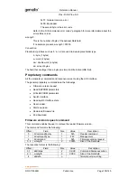
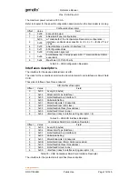
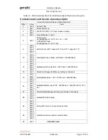
0x02 

dwFeatures = 00010230h 
00000010h: Automatic ICC clock according to parameters 
00000020h: Automatic baud rate according to parameters 
00000200h: NAD value other than 00 accepted 
00010000h: TPDU level exchanges with CCID 
                      APDU/EMV mode 
dwFeatures = 00020472h 
00000002h: Automatic parameter configuration based on ATR data 
00000010h: Automatic ICC clock frequency change 
00000020h: Automatic baud rate according to parameters 
00000040h: Automatic parameters negotiation made by the CCID 
00000400h: Automatic IFSD exchange as first exchange (T=1) 
00020000h: Short APDU level exchange with CCID 

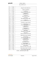
0x01 

0x00 

44 

0x0F 

dwMaxCCIDMessageLength (271 bytes) 

0x01 
0x00 
0x00 

48 

0x00 

bClassGetResponse 

49 

0x00 

bClassEnvelope 

50 

0x00 

wLcdLayout (0 line, 0 character per line) 

0x00 

52 

0x00 

bPINSupport (PIN verification not supported) 

53 

0x01 

bMaxCCIDBusySlots (1 slot can be busy at the time) 

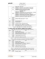
Table 39 – USB Contact Smart Card Device Class Descriptor 

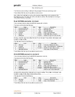
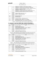
Contact smart card interface endpoint descriptors 

Contact Smart Card Interface Endpoint Descriptor (endpoint 4 Bulk Out ) 

Offset 

Value 

Field 

0x07 

bLength (7 bytes) 

0x05 

bDescriptorType (Endpoint) 

0x04 

bEndpointAddress (b7=0 OUT, b3-b0 = address 4) 

0x02 

bmAttributes (02h =Bulk endpoint) 

0x40 

wMaxPacketSize (64 bytes max) 

0x00 

0x00 

bInterval (For full speed : Ignored) 

Table 40 – USB Contact Smart Card Interface Endpoint Descriptor (Bulk Out) 

Contact Smart Card Interface Endpoint Descriptor (endpoint 5 Bulk In) 

Offset 

Value 

Field 

0x07 

bLength (7 bytes) 

0x05 

bDescriptorType (Endpoint) 

0x85 

bEndpointAddress (b7=1 IN, b3-b0 = address 5 ) 

0x02 

bmAttributes (02h = Bulk endpoint) 

0x40 

wMaxPacketSize (64 bytes max) 

0x00 

0x00 

bInterval (For full speed : Ignored) 

Table 41 – USB Contact Smart Card Interface Endpoint Descriptor (Bulk In) 

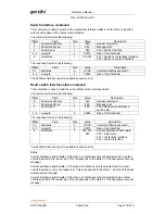
Contact Smart Card Interface Endpoint Descriptor (endpoint 7 Interrupt IN) 

Offset 

Value 

Field 

0x07 

bLength (7 bytes) 

Summary of Contents for Prox-DU

Page 1: ...Reference Manual Prox DU Prox SU www gemalto com DOC118569D Public Use Page 1 145 Prox DU Prox SU Dual interface USB smart card reader Reference Manual ...

Page 2: ... of merchantability fitness for a particular purpose title and non infringement In no event shall Gemalto be liable whether in contract tort or otherwise for any indirect special or consequential damages or any damages whatsoever including but not limited to damages resulting from loss of use data profits revenues or customers arising out of or in connection with the use or performance of informat...

Page 3: ...tion enable GemCore POS Pro chip escape command Linux and Mac USB CCID Class Driver Details paragraph added http catalog update microsoft com web link added Web link for HID libraries added September 2010 C Linux MAC OS support correction Mac OS X Snow Leopard 10 6 is now supported RF parameters considered only when both RF Parameters Usage 01h RF Power Attenuation 0Fh Gem_PC SC V2 picture upgrade...

Page 4: ......

Page 5: ...TALLATION 30 CHECKING THE SMART CARD DETECTION 30 CONFIGURING THE READER WRITER 32 EEPROM PARAMETERS CONTENTS 32 Control parameters 33 EEPROM structure version 33 General parameters 33 Dual interface card protection 33 Card notification delay 34 Communication time out with GemCore POS Pro 34 Load MIFARE Keys security option 34 Contactless automaton parameters 34 Automaton timing 34 Extended ATQB s...

Page 6: ...COMMAND 56 GENERAL AUTHENTICATE COMMAND 58 READ BINARY COMMAND 60 UPDATE BINARY COMMAND 61 ERROR CODE LIST SUMMARY 62 INTERFACING WITH CONTACT CARDS 64 DETECTING AN INSERTION 64 DETECTING A REMOVAL 64 ATR FOR CONTACT SMART CARDS 64 Structures and content 66 Structure of the subsequent characters in the ATR 66 Format character T0 66 Interface characters TAi TBi TCi TDi 67 Historical characters T1 T...

Page 7: ...mand 88 PC_to_RDR_GetSlotStatus command 88 PC_to_RDR_XfrBlock command 88 PC_to_RDR_GetParameters command 90 PC_to_RDR_ResetParameters Command 90 PC_to_RDR_SetParameters command 90 PC_to_RDR_Escape command 92 Switch interface 92 Get firmware version 92 PC_to_RDR_Abort command 92 Response pipe bulk in messages for the contactless interface 93 RDR_to_PC_DataBlock Command 93 RDR_to_PC_SlotStatus Comma...

Page 8: ... card device class descriptor 117 Contact smart card interface endpoint descriptors 118 STRING DESCRIPTORS 119 LangID string descriptor 119 Manufacturer string descriptor 119 Product string descriptor 119 Serial number string descriptor 120 HID interface string descriptor 121 Contactless smart card interface string descriptor 121 Contact smart card interface string descriptor 122 BOOT LOADER 123 H...

Page 9: ...NDARDS AND SPECIFICATIONS 145 TABLE LIST Table 1 Dual interface USB smart card reader writer models 12 Table 2 Prox DU and Prox SU differences 16 Table 3 Environmental Characteristics 20 Table 4 Interface capability 21 Table 5 Supported Operating Systems 26 Table 6 EEPROM parameters contents 33 Table 7 Smart Card Database Query Functions 40 Table 8 Smart Card Database Management Functions 40 Table...

Page 10: ...ial Number String Descriptor 120 Table 47 USB HID Interface String Descriptor 121 Table 48 USB Contactless Smart Card Interface String Descriptor 122 Table 49 USB Contact Smart Card Interface String Descriptor 122 Table 50 Boot loader HID error codes 126 Table 51 USB Boot loader Configuration Descriptor 127 Table 52 USB Boot loader Interface String Descriptor 129 Table 53 LEDs states for the Boot ...

Page 11: ...er window Windows XP 30 Figure 24 USB HID icons in the Device Manager window Windows XP 30 Figure 25 Contactless smart card check 30 Figure 26 Contact smart card check 31 Figure 27 PC SC Architecture 39 Figure 28 Gem_PCSC window 42 Figure 2 Prox DU PC SC name Windows 43 Figure 3 Prox SU PC SC name Windows 43 Figure 4 Prox DU and Prox SU PC SC names Windows 43 Figure 5 Two Prox DU PC SC names Windo...

Page 12: ...nstallation please refer to the Installation Guide document Who Should Read This Book This reference manual is designed for developers of PC SC smart card application or driver For driver design familiarity with the USB protocol is recommended Conventions Bit Numbering A byte consists of 8 bits b7 to b0 where b7 is the most significant bit and b0 is the least significant bit One byte b7 b6 b5 b4 b...

Page 13: ...luding an internal SIM SAM card slot Figure 2 Prox SU view The Prox technology complies with ISO14443 standard related to proximity cards applicable to type A and type B contactless smart cards The Prox technology uses MIFARE a registered trademark of NXP technology as part of its integrated solution The GemCore technology complies with ISO7816 and EMV standard related to contact smart cards Both ...

Page 14: ...d Unique USB serial number which enables that the device can be plugged into any USB slot on a computer without having to re install the driver Standard CCID interface for both smart card slot contact and contactless Standard HID interface for device administration No need of a proprietary USB driver The standard CCID and HID drivers of the computer can be used PC SC V2 0 compliant Embedded protec...

Page 15: ...nctional tests according to BSI TR 03119 attachment B 2 o Installation of the smart card reader on different operating systems o Functional tests related to the use of the nPA smart card as card recognition secret code input or change or online authentication The conformity of the product Prox SU Prox DU with or without the stand to the Technical Guideline BSI TR 03119 has been evaluated by evalua...

Page 16: ...sed the SIM SAM card cannot be removed Figure 5 Prox SU ID 000 size slot The following table shows all the different features supported by the Prox DU and the Prox SU reader writers Feature Prox DU Prox SU Contact card interface ID 1 size format smart card Removable ID 000 size format SIM SAM Not removable Dual interface protection Managed Can be disabled according to device configuration No manag...

Page 17: ...turned of ill be activate witch comma user to com lot rd protection by changing t re available s o have a dua SU device ference Man x DU Prox Public Use on and rt cards simu oid to damag al interface s ed operation o ated when a ard power su activated whe ff to avoid po ed again whe and is send municate w n is enabled b the reader w simultaneous al interface S nual x SU switch ltaneously a ge dual...

Page 18: ...e 8 The contactless smart card is not fully inserted into the Prox DU slot Figure 9 The contactless smart card is fully inserted into the Prox DU slot after the switch activation Note if the contactless smart card is fully inserted into the slot the contactless interface will be deactivated because the contact interface has a higher priority than the contactless interface To activate the contactle...

Page 19: ... a contactless smart card Figure 11 The contactless smart card is put near or over the Prox SU landing zone The Prox SU and a contact SIM SAM card Figure 12 The contact SIM SAM card is inserted into the Prox SU connector Note the SIM SAM card cannot be installed or removed without opening the casing The SIM SAM card is permanently installed into the Prox SU reader The operating distance is a few c...

Page 20: ...g Protection Index Prox DU IP20 open case device Prox SU IP40 dustproof device EEPROM data 10 years minimum retention 100000 erase write cycles Physical Dimensions Without stand 26 mm x 69 mm x 126 mm max height x width x depth With stand 132 mm x 69 mm x 79 mm max height x width x depth Weight Without stand 145 g max With stand 255 g max Cabling Distance 1 80 m USB cable Power Supply Voltage USB ...

Page 21: ...erface Two visual indicators Depending on the smart card type the connectors used will be as shown in the next table Table 4 Interface capability Interface Prox DU Connector type Prox SU Connector type USB USB A plug USB A plug Contact card ISO7810 ID 1 size ISO7816 2 8 pins ISO7810 ID 000 size ISO7816 2 8 pins Contactless card Landing zone No connector Landing zone No connector Visual Indicators ...

Page 22: ...ID driver included into the operating system of the computer is used for the smart card interface The standard USB HID driver included into the operating system of the computer is used for the device administration The selective suspend is not supported by the USB interface Only standard suspend is supported Contactless interface The contactless interface is available with the Prox DU and the Prox...

Page 23: ...s Contact interface The contact interface is available with the Prox DU and the Prox SU and is composed of a smart card connector with a smart card slot located in the front cabinet for the Prox DU and located inside the casing for the Prox SU Figure 15 Contact card slot Prox DU and Prox SU The characteristics for the contact interface are as follows Card type o Asynchronous Microcontroller based ...

Page 24: ...LED interface Two LEDs are available as visual indicators Figure 17 Visual indicators The indicators give information about the smart card interface as described in the next table Card Indicator Description Off The card interface is deactivated Slow Blink 0 2 s 2 s The card interface is ready Blink 0 5 s 1 s The card is present and inactive powered off On The card is present and active powered on ...

Page 25: ...s the w he driver to c on ference Man x DU Prox Public Use eader e USB port of h shortly to in perating syste wizard will aut consider rega Use Window Use Window Inbox Inbox Upon reque Inbox Use the late package ava http suppo Use the late package ava http suppo Use the late package ava http suppo Use the late driver V1 4 0 operating u code availab site http pcsclit tml Use the late installation p...

Page 26: ...R5 0 tem the follow soft com v7 s link http su ail the install s please refe ference Man x DU Prox Public Use Use the late installation p web site http Use the late installation p web site http pported Oper Prox DU and ating system R6 0 except wing web lin site Search a upport gemal ation wizard er to the Co nual x SU est Mac OS 1 package ava p support g est Mac OS 1 package ava p support g rating...

Page 27: ...procedure Windows XP installation without the Windows Update procedure These installation steps will be effective only if the USB CCID diver is available in the operating system When the USB cable is plugged into the USB port of the computer the following popup dialog boxes will be successively displayed over the task bar Found New Hardware Prox Dual USB PC LinkReader Found New Hardware Prox Dual ...

Page 28: ...ation steps will be effective if the USB CCID diver not available in the operating system When the USB cable is plugged into the USB port of the computer the previous popup windows and the following wizard will appear Figure 19 Windows XP Installation wizard first window Click the Yes this time only button to start the Windows Update procedure Found New Hardware USB Smart Card reader Found New Har...

Page 29: ...l located on the back of the reader writer Figure 20 Windows XP Installation wizard second window Click the Install the software automatically Recommended button Click the Next button to continue Figure 21 Windows XP Installation wizard third window The Windows Update procedure will be running Wait until the installation is completed Figure 22 Windows XP Installation wizard final window ...

Page 30: ...ktop b Select the Properties menu c Select the Hardware tab d Click the Device Manager button e Click the Smart card readers icon Two USB Smart Card reader icons should be displayed as shown in the next figure Figure 23 USB smart card reader icons in the Device Manager window Windows XP f Click the Human Interface Devices icon Two HID devices icons should be displayed as shown in the next figure F...

Page 31: ...ange will occur To check if the Prox DU reader writer is able to detect contact smart cards insert a smart card into the reader writer slot The yellow LED should be set to an enlightened state Figure 26 Contact smart card check Note The yellow LED should return to the blinking state after a short time depending on the computer operating system The smart card used for the check should be of course ...

Page 32: ...y the user EEPROM parameters contents The next table shows the EEPROM parameters contents Offset Usage Default Value Control parameters 0 EEPROM structure version 08h General parameters 1 Dual interface card protection 00h 2 Card notification delay x 100 ms 01h 3 Communication time out with GemCore POS Pro x10 sec 11h 4 Load MIFARE keys security option 00h 5 to 8 RFU 4 bytes 00h Contactless automa...

Page 33: ...h EEPROM parameters Validity 65 CRC control 5Bh Table 6 EEPROM parameters contents Control parameters EEPROM structure version This byte defines the structure of the parameters in the EEPROM At start up if the structure version is not the same than the structure version known by the firmware the EEPROM is reinitialized General parameters These bytes define the general behavior of the device Dual i...

Page 34: ...t cards b0 b3 periodic time to search or check for a card presence unit 100 ms 0 1 sec to 1 6 sec 0 is not allowed b7 b4 release time after the last host command unit 1 second 1 to 16 sec 0 is not allowed Extended ATQB support This byte defines the Extended ATQB support option as defined in the ISO14443 standard 00h Extended ATQB is not supported 01h Extended ATQB is supported When this byte 01h t...

Page 35: ...1 b1 is used to stop the polling of ISO14443 B smart cards when set to 1 b7 is used to perform a RF reset before each REQ command when set to 1 b7 b6 b5 b4 b3 b2 b1 b0 Bit rate RFU RFU RFU RFU RFU RFU X 1 Type A card polling is disabled RFU RFU RFU RFU RFU RFU 1 X Type B card polling is disabled 0 RFU RFU RFU RFU RFU X X A RF reset is not performed before each REQ command 1 RFU RFU RFU RFU RFU X X...

Page 36: ...00h default value is used 01h to FFh time 5 to 1275 ms unit 5 ms RF Parameters Usage This byte defines the usage of the RF Parameters for ISO14443 A and ISO14443 B 00h default values are used 01h user defined values in RF parameters for type A and Type B card are used RxThreshold RFCfg TypeB Note The user defined values must be used only for tuning purpose RF Power Attenuation The byte defines the...

Page 37: ...ameters refer to the MFRC523 contactless controller IC documentation EEPROM Parameters Validity CRC control This byte controls the EEPROM parameters validity MAD CRC algorithm is used to compute the CRC value from offset 0 to 64 At startup if the EEPROM parameters validity is not correct all the parameters are set to their default value That CRC should be updated at each modification into the EEPR...

Page 38: ...ucMadCrc unsigned char _uc_len unsigned char _puc_in unsigned char _puc_out unsigned char u_i unsigned char u_j unsigned char uc_status uc_status ERR_OK _puc_out 0xC7 bit swapped 0xE3 for u_j 0 u_j _uc_len u_j _puc_out _puc_out _puc_in u_j for u_i 0 u_i 8 u_i if _puc_out 0x80 _puc_out _puc_out 1 0x1D else _puc_out _puc_out 1 if _puc_out uc_status ERR_MAD_CRC return uc_status 0x00 if last byte is t...

Page 39: ...ng on various platforms platform neutral Enable applications to take advantage of products and components from multiple manufacturers vendor neutral Enable the use of advances in technology without rewriting application level software application neutral Facilitate the development of standards for application level interfaces to smart card services in order to enhance the fielding of a broad range...

Page 40: ...ve a reader from the system SCardForgetReaderGroup Remove a reader group from the system SCardIntroduceCardType Introduce a new card to the system SCardIntroduceReader Introduce a new reader to the system SCardIntroduceReaderGroup Introduce a new reader group to the system SCardRemoveReaderFromGroup Remove a reader from a reader group Table 8 Smart Card Database Management Functions Resource Manag...

Page 41: ...g data using T 0 T 1 and raw protocols SCardConnect Connect to a card SCardReconnect Reestablish a connection SCardDisconnect Terminate a connection SCardBeginTransaction Start a transaction blocking other applications from accessing a card SCardEndTransaction End a transaction allowing other applications to access a card SCardStatus Provide the current status of the reader SCardTransmit Requests ...

Page 42: ...69D Public Use Page 42 145 Gem_PC SC software tool The Gemalto Gem_PCSC tool may help to become familiar with the PC SC environment Figure 28 Gem_PCSC window The Gem_PCSC tool is available for download in the Gemalto support website http support gemalto com ...

Page 43: ...on the rear cabinet The next figure displays the name for one Prox DU connected to the computer Figure 29 Prox DU PC SC name Windows The next figure displays the name for one Prox SU connected to the computer Figure 30 Prox SU PC SC name Windows The next figure displays the name for one Prox DU and one Prox SU both connected to the computer Figure 31 Prox DU and Prox SU PC SC names Windows The nex...

Page 44: ...bel located on the rear cabinet The next figure displays the name for one Prox DU connected to the computer Figure 33 Prox DU PC SC name Linux The next figure displays the name for one Prox SU connected to the computer Figure 34 Prox SU PC SC name Linux The next figure displays the name for one Prox DU and one Prox SU both connected to the computer Figure 35 Prox DU and Prox SU PC SC names Linux T...

Page 45: ...ing the T 0 protocol will not be accepted by the contactless interface Multi activation of contactless smart cards is not supported Consequently the first smart card detected in front of the reader writer will be activated The remaining smart cards will be ignored The communication with the contactless interface and the contact interface shall be exclusive Consequently the application shall not us...

Page 46: ...nd ISO14443 B cards are polled with a default periodic rate of 100 ms Note Multi activation of contactless smart cards is not supported by the Prox DU and the Prox SU devices The first smart card detected in front of the reader writer will be activated When a smart card insertion is detected a CCID insertion notification message will be generated and the blue LED of the contactless reader writer w...

Page 47: ...Tk Historical bytes ISO14443A The historical bytes from ATS response Refer to the ISO14443 4 specification ISO14443B Byte 1 4 Application Data from ATQB Byte 5 7 Protocol Info Byte from ATQB Byte 8 Higher nibble MBLI from ATTRIB command Lower nibble RFU 0 Refer to the ISO14443 3 specification 4 N UU TCK Exclusive OR of bytes T0 to Tk Table 14 ATR for contactless Smart cards The contactless smart c...

Page 48: ...Lite R2 STD smart card will be 3Bh 8Bh 80h 01h 80h 31h 80h 65h B0h 07h 02h 02h 89h 83h 00h E3h With n Bh 11 historical bytes Historical bytes from the ATS response 80h 31h 80h 65h B0h 07h 02h 02h 89h 83h 00h UU E3h TCK The ATR returned by a GemCombi CDLite smart card will be 3Bh 80h 80h 01h 01h With n 0h no historical byte UU 01h TCK ...

Page 49: ...DU command after the selection process the native commands are no more available The command is formatted as follows CLA INS P1 P2 Lc Data In FFh DEh 00h 00h N DESFire Command 1 byte 1 byte 1 byte 1 byte 1 byte N bytes The response is formatted as follows Data Out SW1 SW2 M bytes 1 byte 1 byte Where N Length of the Data In field Length of the native command Data In DESFire native command Refer to ...

Page 50: ...Reference Manual Prox DU Prox SU www gemalto com DOC118569D Public Use Page 50 145 AFh 04h 01h 01h 00h 02h 18h 05h example Refer to the DESFire datasheet for more information about the response ...

Page 51: ...e Data Out Requested information Refer to the ISO14443 standard SW1 SW2 Command execution status added by the reader Command executed successfully 90h 00h Others 67h 00h 6Bh 00h 6Ch xxh 62h 82h Wrong length Wrong P1 or P2 Wrong length XX is required End of data reach before Le bytes Note When the requested information does not correspond to the current smart card type ISO14443 A or ISO14443 B an e...

Page 52: ...byte MIFARE memory contactless smart card arranged as 64 memory blocks as shown in the appendix MIFARE cards mapping The MIFARE 4K is a 32 Kbit 4 Kbytes MIFARE memory contactless smart card arranged as 256 memory blocks as shown in the appendix MIFARE cards mapping The MIFARE Ultralight is a 512 bit 64 bytes MIFARE memory contactless smart card arranged as 16 memory pages as shown in the appendix ...

Page 53: ...yte N 1 2 80h TD1 Higher nibble 8 means no TA2 TB2 TC2 only TD2 is following Lower nibble 0 means T 0 3 01h TD2 Higher nibble 0 means no TA3 TB3 TC3 TD3 following Lower nibble 1 means T 1 4 to 2 n 80h T1 Tk Category indicator byte 80h means a status indicator may be present in an optional COMPACT TLV data object 4Fh Application identifier presence indicator LL Length A0h 00h 00h 03h 06h 5 bytes fo...

Page 54: ...1 1 1 1 1 RFU Table 16 SS Byte for Standard Card Name Two bytes identifier MIFARE Standard 1K 00h 01h MIFARE Standard 4K 00h 02h MIFARE Ultralight 00h 03h MIFARE Mini 00h 26h Table 17 NN Bytes for Card Name The ATR returned by a MIFARE Standard 1K will be 3Bh 8Fh 80h 01h 80h 4Fh 0Ch A0h 00h 00h 03h 06h 03h 00h 01h 00h 00h 00h 00h 6Ah With LL 0Ch 12 bytes SS 03h ISO14443 A part 3 NN NN 00h 01h MIFA...

Page 55: ...03h ISO14443 A part 3 NN NN 00h 26h MIFARE Mini UU 4Dh TCK Get Data command This command is used to retrieve information about the inserted smart card This command can be used for all kinds of contactless cards The command is formatted as follows CLA INS P1 P2 Lc Data Le FFh CAh INF 00h NN 1 byte 1 byte 1 byte 1 byte 1 byte The response is formatted as follows Data SW1 SW2 NN bytes 1 byte 1 byte W...

Page 56: ...anti collision process Consequently the first byte received will be at index zero The bit order of the string bytes must be such that the LSB MSB matches with the LSB MSB of the card defined UID Historical bytes of the ATS Refer to ISO14443 A standard For a MIFARE or ISO14443 B card that command is not supported SW1 SW2 Command execution status Command executed successfully 90h 00h Others Refer to...

Page 57: ... 79 00h to 4Fh are reserved for the non volatile key stored in EEPROM The key number 80 to 159 50h to 9Fh are reserved for the volatile key stored in RAM KL Key Length KL 06h means 6 bytes long KL 0Ch means 12 bytes long if the Load MIFARE key security bit is set on Key MIFARE Secret Key The MIFARE key value Should be followed by the Gemalto Transport key if the Load MIFARE key security bit is set...

Page 58: ...rned Key number not valid Note After delivery the non volatile keys stored in EEPROM number 0 to 79 are initialized to a default value The keys number 00 to 39 are initialized with value A0h A1h A2h A3h A4h A5h The keys number 40 to 79 are initialized with value B0h B1h B2h B3h B4h B5h Note Each time the Prox DU and the Prox SU is powered the volatile keys stored in RAM number 80 to 159 are initia...

Page 59: ...ddress Block MSB 00h ABLL Address Block LSB MIFARE 1K MIFARE 4K MIFARE Mini 00h 3Fh 00h FFh 00h 13h KT Key Type Key A 60h Key B 61h KN Key Number MIFARE Key Number 0 to 159 00h to 9Fh The key number 0 to 79 are reserved for the non volatile key stored in EEPROM The key number 80 to 159 are reserved for the volatile key stored in RAM SW1 SW2 Command execution status Command executed successfully 90...

Page 60: ...ed as follows CLA INS P1 P2 Lc FFh B0h ABLM ABLL Size 1 byte 1 byte 1 byte 1 byte 1 byte The response is formatted as follows Data SW1 SW2 16 bytes 1 byte 1 byte Where ABLM Address Block MSB 00h ABLL Address Block LSB MIFARE 1K MIFARE 4K MIFARE Mini MIFARE Ultralight 00h 3Fh 00h FFh 00h 13h 00h 0Fh Size Size of the memory area MIFARE 1K 4K Mini MIFARE Ultralight 10h size of the memory block 04h si...

Page 61: ... Binary command is used to write data into a MIFARE memory area Data consist of a memory block 16 bytes or a memory page 4 bytes This command is formatted as follows CLA INS P1 P2 Lc DATA FFh D6h ABLM ABLL Size Data 1 byte 1 byte 1 byte 1 byte 1 byte 16 bytes The response is formatted as follows SW1 SW2 1 byte 1 byte Where ABLM Address Block MSB 00h ABLL Address Block LSB MIFARE 1K MIFARE 4K MIFAR...

Page 62: ...data reach before Le bytes Le is greater than data length 67h 00h Wrong length 6Ah 81h Function not supported 6Bh 00h Wrong parameter P1 P2 6Ch XXh Wrong length wrong number Le XX is the exact number if Le is less than the available data length 6Dh 00h Instruction code not supported Load Keys error codes 65h 81h Memory failure 67h 00h Wrong length 69h 83h Reader key not supported 69h 85h Secure tr...

Page 63: ...ity not satisfied 69h 85h Address out of range 6Ah 81h Function not supported 6Ch XX Wrong length wrong number Le XX is the exact number if Le is less than the available data length Update Binary error codes 67h 00h Wrong length 69h 82h Security not satisfied 69h 85h Address out of range 6Ah 81h Function not supported Table 18 Memory card error codes ...

Page 64: ...detect a smart card insertion or removal the SIM SAM card will always be considered as inserted when the SIM SAM card is into its connector Detecting an Insertion The contact reader writer will check if a smart card is inserted into the slot When a smart card insertion is detected its properties are recorded and a CCID insertion notification message will be generated Detecting a Removal A smart ca...

Page 65: ...haracters Optional Strutctural encodes Y2 and T 6 XX TA2 Interface characters Optional Global specific mode byte 7 XX TB2 Interface characters Optional Global deprecated 8 XX TC2 Interface characters Optional Specific to T 0 9 Y3 T TD2 Interface characters Optional Structural encodes Y3 and T For i 2 Yi T TDi 1 Interface characters Optional Structural encodes Yi and T XX TAi Interface characters O...

Page 66: ... falls outside the scope of this part of ISO7816 For simplicity T0 TAi TCK will designate the bytes as well as the characters in which they are contained Structure of the subsequent characters in the ATR The initial character TS is followed by a variable number of subsequent characters in the following order The format character T0 and optionally the interface characters TAi TBi TCi TDi and the hi...

Page 67: ... TBi for b5 character TCi for b6 character TDi for b7 are or are not depending on whether the relevant bit is 1 or 0 transmitted subsequently in this order after the character containing Yi When needed the interface device shall attribute a default value to information corresponding to a non transmitted interface character When TDi is not transmitted the default value of Yi 1 is null indicating th...

Page 68: ...rotocol but only qualifies global interface bytes Note If only T 0 is indicated TCK shall not be sent In all other cases TCK shall be sent Specifications of the global interface bytes Among the interface bytes possibly transmitted by the smart card in answering to reset this subclaus defines only the global interface bytes TA1 TB1 TC1 TA2 TB2 the first TA for T 15 and the first TB for T 15 These g...

Page 69: ...smitted by the smart card or the interface device GT 12 etu R N f If T 15 is absent in the Answer to Reset then R F D i e the integers used for computing the etu If T 15 is present in the Answer to Reset then R Fi Di i e the integers defined above by TA1 No extra guard time is used to transmit characters from the card GT 12 etu The use of N 255 is protocol dependent GT 12 etu in PPS and in T 0 For...

Page 70: ...22 clock stop indicator X According to the next table 10 bits 5 to 1 indicate the classes of operating conditions accepted by the smart card Each bit represents a class bit 1 for class A bit 2 for class B and bit 3 for class C Bits 5 to 0 00 0001 00 0010 00 0100 00 0011 Y A only 5V B only 3V C only 1 8V A and B Bits 5 to 0 00 0110 00 0111 Any other value Y B and C A B and C RFU Table 23 class indi...

Page 71: ...e CCID model assumes that a smart card is or can be inserted into the device This is the purpose for the slot change interrupt message Also this model applies to devices that integrate CCID and smart card functionalities and may be viewed as containing a permanently inserted smart card CCID communication pipes The CCID device uses the following USB communication pipes A control pipe o To monitor t...

Page 72: ...rfaces TPDU level of exchange For TPDU level exchanges the CCID provides the transportation of host s TPDU to the smart card s TPDU The TPDU format changes according to the protocol or for PPS exchange TPDU for PPS exchange has the following format Command TPDU FF PPS0 PPS1 PPS2 PPS3 PCK with PPS1 PPS2 PPS3 optional Response TPDU FF PPS0_R PPS1_R PPS2_R PPS3_R PCK_R with PPS1_R PPS2_R PPS3_R optio...

Page 73: ...eived is optional The interpretation of first bytes received as NAD and PCB to manage VPP is optional and depends on CCID capabilities APDU level of exchange For APDU level exchanges the CCID provides the transportation of host s APDU to the smart card s TPDU APDU commands and responses are defined in ISO7816 4 Two APDU levels are defined short APDU and extended APDU Short APDU and extended APDU a...

Page 74: ...en deactivated and newly inserted After resuming the CCID will do two things in no particular order 1 Send the RDR_to_PC_NotifySlotChange message to inform the driver which slots have newly inserted cards 2 The CCID will reactivate the smart cards only from a PC_to_RDR_IccPowerOn message from the driver or automatically if the CCID has the automatic activation on insertion feature Note When reacti...

Page 75: ...or it deactivates the card and makes no further attempts to obtain a response from the card Slot in TPDU Mode The command is compliant with the ISO7816 3 standard If the command fails the card is powered off Because it does not parse the ATR the reader does not store parameters To meet card requirements the host must send a PC_to_RDR_SetParameters command to set the baud rate the protocol etc Refe...

Page 76: ...mmand This command will be rejected if no contact smart card is declared present and active This command is handled differently depending on what mode the slot is in Slot in APDU EMV Mode The command is exchanged between the reader and the host using APDU commands As the reader exchanges TPDU commands with the card it formats the command using the T 0 or T 1 protocol depending on the fields of the...

Page 77: ...s used to retrieve the current slot parameters It is always accepted Offset Field Size Value Description 0 bMessageType 1 6Ch PC_to_RDR_GetParameters 1 bwLength 4 00000000h 5 bSlot 1 00h Slot 0 6 bSeq 1 00 FFh Sequence number for the command 7 abRFU 3 000000h Reserved for future used The response to this command message is the RDR_to_PC_Parameters response message PC_to_RDR_ResetParameters command...

Page 78: ... conversion factor see table Fi Di of ISO 7816 3 11 bmTCCKST0 1 00h 02h For T 0 b0 0b b7 2 000000b b1 0 direct convention b1 1 inverse convention CCID ignores bit b1 12 bGuardTimeT0 1 00h FFh Extra Guard Time between two characters Add 0 to 254 etu to the normal guard time 12 etu FFh is the same as 00h 13 bWaitingIntegerT0 1 00h FFh WI for T 0 used to define WWT 14 bClockStop 1 00h ICC clock stop ...

Page 79: ...h Slot 0 6 bSeq 1 00 FFh Sequence number for the command 7 abRFU 3 000000h Reserved for Future Used 10 abData Byte array Data block sent to the CCID The response to this message is the RDR_to_PC_Escape response message Note the Microsoft CCID USB driver parameters should be customized to process the CCID Escape Command because this feature is not enabled by default Refer to the Enabling the CCID E...

Page 80: ...e implemented for the contact interface RDR_to_PC_DataBlock RDR_to_PC_SlotStatus RDR_to_PC_Parameters RDR_to_PC_Escape The following CCID message is not implemented RDR_to_PC_DataRateAndClockFrequency RDR_to_PC_DataBlock This message is the response to the PC_to_RDR_IccPowerOn and PC_to_RDR_XfrBlock commands For the PC_to_RDR_PowerOn command this response message contains the ATR of the card For t...

Page 81: ... OUT message 7 bStatus 1 00h 01h 02h 40h 41h 42h Slot status register 0Xh no error 4Xh command failed X 0 card present and active X 1 card present and inactive X 2 card not present 8 bError 1 00h FFh Slot error register Error when bStatus 4Xh 9 bClockStatus 1 00h Value 00h Clock running RDR_to_PC_Parameters This message is the response to the PC_to_RDR_GetParameters PC_to_RDR_ResetParameters and P...

Page 82: ...r T 0 used to define WWT 14 bClockStop 1 00h ICC clock stop support 00h Stopping the clock is not allowed Protocol data structure for protocol T 1 bProtocolNum 1 dwLength 00000007h Offset Field Size Value Description 10 bmFindexDindex 1 b7 4 FI selecting a clock rate conversion factor b3 0 DI selecting a baud rate conversion factor 11 bmTCCKST1 1 10h 11h 12h 13h For T 1 b7 2 000100b b0 0b Checksum...

Page 83: ...ent from CCID Reporting slot error and slot status registers in bulk in messages for the contact interface Each bulk in message contains the values of the Slot Error register bError and the Slot Status register bStatus Slot error register when bmCommandStatus 1 Error Code Error Name Possible cases FFh CMD_ABORTED Host aborted the current activity FEh ICC_MUTE CCID time out while talking to the ICC...

Page 84: ...0 Processed without error 1 Failed error code provided by error register 2 Time Extension is requested 3 RFU Table 25 Slot Status register When the bmCommandStatus field is 0 indicating the command processed without error or when the bmCommand field is an RFU value then the slot s error register is RFU When the bmCommandStatus field is 1 indicating the command failed then the slot s error register...

Page 85: ... the RDR_to_PC_NotifySlotChange message is implemented The RDR_to_PC_HardwareError message is not implemented RDR_to_PC_NotifySlotChange This message is sent whenever the CCID device detects a change in the insertion status of an ICC slot If an ICC is either inserted or removed from a slot this message must be sent The presence of this message means to the host driver that a change has occurred It...

Page 86: ...act smart card Interface only slot 0 is defined Therefore bSlotICCState can have the following value 00h no ICC present no change since the last RDR_to_PC_NotifySlotChange message was sent 01h ICC present no change since the last RDR_to_PC_NotifySlotChange message was sent 02h no ICC present the slot has changed state since the last RDR_to_PC_NotifySlotChange message was sent 03h ICC present the s...

Page 87: ...e not implemented PC_to_RDR_IccClock PC_to_RDR_T0APDU PC_to_RDR_Secure PC_to_RDR_Mechanical PC_to_RDR_SetDataRateAndClockFrequency In the following paragraphs for all the command messages bSlot must be set to 00h bSeq is not checked PC_to_RDR_IccPowerOn command This command acts like a power on of a contact card Cold reset and warm reset are possible but the pseudo ATR will be always the same This...

Page 88: ...DR_to_PC_SlotStatus response message PC_to_RDR_GetSlotStatus command This command is used to retrieve the current slot status No ICC is present o No card detected in the RF field An ICC is present and inactive o A card is present but the PC_to_RDR_PowerOn command was not executed An ICC is present and active o A card is present and the PC_to_RDR_PowerOn command was successfully executed Offset Fie...

Page 89: ... CCIDs Block Waiting Timeout for this current transfer The CCID will timeout the block after this number multiplied by the block Waiting Time has expired 8 wLevelParameter 2 xxxxh Use changes depending of the exchange level reported by the class descriptor in dwFeature field For the contactless interface Extended APDU level Indicate if an APDU command begins and ends with this command 0000h The AP...

Page 90: ...d PC_to_RDR_SetParameter or set to default value with the command PC_toRDR_ResetParameter to be send back in the response message RDR_to_PC_Parameters The response to this command message is the RDR_to_PC_Parameters response message PC_to_RDR_ResetParameters Command This command is used to reset the current slot parameters Offset Field Size Value Description 0 bMessageType 1 6Dh PC_to_RDR_ResetPar...

Page 91: ...l data structure for protocol T 0 bProtocolNum 0 dwLength 00000005h Offset Field Size Value Description 10 bmFindexDindex 1 b7 4 FI selecting a clock rate conversion factor b3 0 DI selecting a baud rate conversion factor 11 bmTCCKST0 1 00h 02h For T 0 b0 0b b7 2 000000b b1 0 direct convention CCID ignores bit b1 12 bGuardTimeT0 1 00h FFh Extra Guard Time between two characters Add 0 to 254 etu to ...

Page 92: ...dData field is described in the following paragraph The response to this message is the RDR_to_PC_Escape response message Note the Microsoft CCID USB driver parameters should be customized to process the CCID Escape Command because this feature is not enabled by default Refer to the Enabling the CCID Escape Command feature into the driver paragraph for more information The Linux and Mac CCID USB d...

Page 93: ...to_RDR_XfrBlock command messages For the PC_to_RDR_PowerOn commande message this response message contains the pseudo ATR data associated with the contactless card For the PC_to_RDR_XfrBlock command message this response message contains the card response If the card is a T CL card The card response is send as it Only the concatenated data of the INF field of the T CL block The full extended APDU ...

Page 94: ...eType 1 81h RDR_to_PC_SlotStatus 1 bwLength 4 00000000h 5 bSlot 1 00h Slot number Same as Bulk Out message 6 bSeq 1 00 FFh Sequence number Same as Bulk Out message 7 bStatus 1 00h 01h 02h 40h 41h 42h Slot status register 0Xh no error 4Xh command failed X 0 card present and active X 1 card present and inactive X 2 card not present 8 bError 1 00h FFh Slot error register Error when bStatus 4Xh 9 bClo...

Page 95: ...data structure for protocol T 0 bProtocolNum 0 dwLength 00000005h Offset Field Size Value Description 10 bmFindexDindex 1 b7 4 FI selecting a clock rate conversion factor b3 0 DI selecting a baud rate conversion factor 11 bmTCCKST0 1 00h 02h For T 0 b0 0b b7 2 000000b b1 0 direct convention used 12 bGuardTimeT0 1 00h FFh Extra Guard Time between two characters Add 0 to 254 etu to the normal guard ...

Page 96: ... CCID The default values are the following bmFindexDindex 11h bmTCCKST1 10h bGuardTimeT1 00h bWaitingIntegersT1 4Dh bClockStop 00h bIfsc 20h bNadValue 00h RDR_to_PC_Escape Command This message is the response to the PC_to_RDR_Escape command Offset Field Size Value Description 0 bMessageType 1 83h RDR_to_PC_Escape 1 bwLength 4 Size of the abData field 5 bSlot 1 00h Slot number Same as Bulk Out mess...

Page 97: ...ved from a slot this message must be sent The presence of this message means to the host driver that a change has occurred It is possible for more than one change to occur between deliveries of RDR_to_PC_NotifySlotChange messages When the USB bus is resumed from a suspended state both the CCID and the host driver must make identical assumptions about the state of the ICC slots For simplicity the s...

Page 98: ...ing value 00h no ICC present no change since the last RDR_to_PC_NotifySlotChange message was sent 01h ICC present no change since the last RDR_to_PC_NotifySlotChange message was sent 02h no ICC present the slot has changed state since the last RDR_to_PC_NotifySlotChange message was sent 03h ICC present the slot has changed state since the last RDR_to_PC_NotifySlotChange message was sent ...

Page 99: ... must be added and set to a non zero value under the HKLM SYSTEM CCS Enum USB Vid Pid Device Parameters key Then the vendor IOCTL for the Escape command is defined as follows define IOCTL_CCID_ESCAPE SCARD_CTL_CODE 3500 With the enabled Escape Command security against malicious escape commands becomes the reader s responsibility USB CCID readers should implement the GET_CLOCK_FREQUENCIES and GET_D...

Page 100: ... Command feature into the Microsoft driver To enable the CCID Escape Command feature with a Prox DU or Prox SU reader writer the following operations should be performed to customize the Microsoft CCID driver 1 First find in your computer the USB information related to the two USB Smart Card readers Open the Device Manager window to display the two devices Double click on the first icon to get the...

Page 101: ...using the USB information previously recovered o Open the appropriate folder HKLM SYSTEM CCS Enum USB Vid Pid Device Parameters o Click the Edit New DWORD Value menu o Rename the new key EscapeCommandEnable o Double click the new key to edit it and set the value to 1 Perform the operation for the first USB Smart Card readers USB VID_08E6 PID_5503 MI_01 6 1CE7978 3 0001 in the example Perform the o...

Page 102: ... and Mac CCID class driver is also compatible with the USB Chip Smart Card Interface Devices CCID Specification revision 1 0 or later The following web site http pcsclite alioth debian org ccid html is proposing a package that provides the source code for a generic USB CCID Chip Smart Card Interface Devices driver and ICCD Integrated Circuit s Card Devices The main CCID ICCD features supported are...

Page 103: ...rd 10 6 o Leopard 10 5 o Tiger 10 4 CCID Escape Control Code for Linux and Mac Operating Systems The application should use the following control code to send the escape command define IOCTL_CCID_ESCAPE SCARD_CTL_CODE 1 Defining the vendor IOCTL for the CCID Escape Commands supported by the Prox DU or Prox SU reader writer Get firmware version Switch interface ...

Page 104: ...coded using the following format Offset Field Size Value Description 0 bCommandFamily 1 XX Code of the command family 1 bCommandType 1 XX Code of the command type 2 bCommand 1 XX Code of the command 3 4 wLength 2 XXXX Size of the Data field 5 x XX Optional Data of the command bCommandFamily 52h Reader command 53h Bootloader command bCommandType F8h Management command F9h Download Management bInstr...

Page 105: ...prietary commands and response are sent using the HID interface The general proprietary commands are the followings Firmware version request Read EEPROM parameters Write EEPROM parameters Switch interface Read switch interface state Reset reader Start download Download firmware file End download Firmware version request command This command enables the user to retrieve the reader firmware version ...

Page 106: ... 42h The response format is the following Offset Field Size Value Description 0 1 abStatus 2 XX XX Command Status execution 2 3 wLength 2 00XXh Size of the Data field 2 bNbBytes 4 bNbBytes 1 01h 42h Number of byte read 1 to 66 5 abDataEEPROM n Data read in the EEPROM The abStatus field can report a possible execution error Write EEPROM parameters command This command allows writing the EEPROM para...

Page 107: ... Field Size Value Description 0 bCommandFamily 1 52h Reader command 1 bCommandType 1 F8h Management 2 bCommand 1 03h 03h Read current interface switch state 3 4 wLength 2 0000h Size of the Data field The response format is the following Offset Field Size Value Description 0 1 abStatus 2 XX XX Command Status execution 2 3 wLength 2 0001h Size of the Data field 4 bInferface 1 00h 01h 02h Current int...

Page 108: ...alid byte is cleared for the boot loader to stay in download operations An acknowledge is sent to the Host using the HID interface The reader is restarted using the microcontroller watch dog If the reader already runs in the boot mode that means that the user pushed the rescue button The indicator ApplicationValid byte is NOT cleared it allows the user to reboot the reader start the previous appli...

Page 109: ...s Windows Linux Mac OS X This library supports all the commands listed in the previous paragraph The HID libraries are available in the following web link http support gemalto com HID Commands Error Codes In the following table The MSB byte correspond to the first byte reported in the abStatus field of the HID response The LSB byte correspond to the second byte reported in the abStatus field of th...

Page 110: ...f Prox Dual reader Gemalto_Prox_SU product name of Prox SU reader Separator Release version Vx yz release version number x yz Separator Customer G Gemalto Casing Usage XD Official release W working release Order number nn incremental number for each version 00 to 99 It restarts to 00 when the release version number is incremented Boot loader string version The string version of the boot loader res...

Page 111: ... 0x00 bDeviceSubClass 6 0x00 bDeviceProtocol 7 0x20 bMaxPacketSize0 Max packet size Endpoint 0 32 bytes 8 0xE6 IdVendor 0x08E6 0x08 10 XX IdProduct 0x5502 0x5503 0x5504 0x55 12 0x00 BcdDevice 0x0100 Device release number 1 00 0x01 14 0x01 iManufacturer Index of string descriptor manufacturer 1 15 0x02 iProduct Index of string descriptor product 2 16 0x03 iSerialNumber Index of string descriptor de...

Page 112: ...card and contact smart card interfaces is Smart Card CCID These two interfaces have three endpoints HID Interface Descriptor Offset Value Field 0 0x09 bLength 9 bytes 1 0x04 bDescriptorType Interface 2 0x00 bInterfaceNumber Interface 1 3 0x00 bAlternateSetting 4 0x01 bNumEndpoints 1 Endpoints 5 0x03 bInterfaceClass HID class 6 0x00 bInterfaceSubClass No subclass 7 0x00 bInterfaceProtocol none 8 0x...

Page 113: ...r Device Class Descriptors HID class descriptor HID Class Descriptor Offset Value Field 0 0x09 bLength 9 bytes 1 0x21 bDescriptorType 2 0x00 0x01 bcdHID 1 00 4 0x00 bCountryCode not supported 5 0x01 bNumDescriptors 1 report 6 0x22 bDescriptorType 7 0x32 0x00 wDescriptorLength 50 bytes Table 32 USB HID Class Descriptor HID interface endpoint descriptor HID Interface Endpoint Descriptor endpoint 4 I...

Page 114: ...rt Usage ID Vendor defined 03 22 03 23 15 Output Report Logical Minimum 0 24 00 25 26 Output Report Logical Maximum 255 26 FF 27 00 28 75 Output Report Report Size 8 8 bits per data 29 08 30 96 Output Report Report Count 0x116 278 x 8bits 31 16 32 01 33 91 Output Data Variable Absolute 34 02 35 09 Feature Report Usage ID Vendor defined 04 36 04 37 15 Feature Report Logical Minimum 0 38 00 39 26 Fe...

Page 115: ...aultClock 4 MHz 4000 KHz 0x00000FA0 0x0F 0x00 0x00 14 0xA0 dwMaximumClock 4 MHz 4000 KHz 0x00000FA0 0x0F 0x00 0x00 18 0x00 bNumClockSupported Manual setting not allowed 19 0x00 dwDataRate clock 372 10752 bps 0x00002A00 0x2A 0x00 0x00 23 0x00 dwDataRate clock 372 10752 bps 0x00002A00 0x2A 0x00 0x00 27 0x00 bNumDataRatesSupported manual setting not allowed 28 0xFE dwMaxIFSD 254 bytes Frame T CL 251 ...

Page 116: ...Interface Endpoint Descriptor endpoint 1 Bulk Out Offset Value Field 0 0x07 bLength 7 bytes 1 0x05 bDescriptorType Endpoint 2 0x01 bEndpointAddress b7 0 OUT b3 b0 address 1 3 0x02 bmAttributes 02h Bulk endpoint 4 0x40 wMaxPacketSize 64 bytes max 0x00 6 0x00 bInterval For full speed Ignored Table 36 USB Contactless Smart Card Interface Endpoint Descriptor Bulk Out Contactless Smart Card Interface E...

Page 117: ...Support 0x01 5V 6 0x03 dwProtocols b0 1 supports T 0 and b1 1 supports T 1 0x00 0x00 0x00 10 0xA0 dwDefaultClock 4 MHz 4000 KHz 0x00000FA0 0x0F 0x00 0x00 14 0xA0 dwMaximumClock 4 MHz 4000 KHz 0x00000FA0 0x0F 0x00 0x00 18 0x00 bNumClockSupported Manual setting not allowed 19 0x00 dwDataRate clock 372 10752 bps 0x00002A00 0x2A 0x00 0x00 23 0x20 dwMaxDataRate clock D F 500000 bps 0x0007A120 for TA1 9...

Page 118: ...fication not supported 53 0x01 bMaxCCIDBusySlots 1 slot can be busy at the time Table 39 USB Contact Smart Card Device Class Descriptor Contact smart card interface endpoint descriptors Contact Smart Card Interface Endpoint Descriptor endpoint 4 Bulk Out Offset Value Field 0 0x07 bLength 7 bytes 1 0x05 bDescriptorType Endpoint 2 0x04 bEndpointAddress b7 0 OUT b3 b0 address 4 3 0x02 bmAttributes 02...

Page 119: ... bLength 12 1 0x03 bDescriptorType String 2 0x09 wLangID 0 U S English 0409h 0x04 Table 43 USB LangID String Descriptor Manufacturer string descriptor String01 index iManufacturer of device descriptor Offset Value Field 0 0x10 bLength 1 0x03 bDescriptorType String 2 G 0 bString Gemalto e 0 m 0 a 0 l 0 t 0 o 0 Table 44 USB Manufacturer String Descriptor Product string descriptor String02 index iPro...

Page 120: ...2 0x00 Table 45 USB Product String Descriptor Serial number string descriptor String03 index iSerialNumber of device descriptor Offset Value Field 0 0x22 bLength 34 bytes 1 0x03 bDescriptorType String 2 SN7 0x00 bString SN7 SN6 SN5 SN4 SN3 SN2 SN1 SN0 The serial number value is the 8 ASCII characters string of the serial number printed on the reader label and bar code SN7 0x00 SN6 0x00 SN6 0x00 SN...

Page 121: ...x 0x00 0x00 D 0x00 U 0x00 0x00 H 0x00 I 0x00 D 0x00 _ 0x00 x 0x00 x 0x00 x 0x00 x 0x00 x 0x00 x 0x00 x 0x00 x 0x00 Table 47 USB HID Interface String Descriptor Contactless smart card interface string descriptor String05 index iInterface of interface descriptor Contactless smart card interface Offset Value Field 0 0x3A bLength 58 bytes 1 0x03 bDescriptorType String 2 P 0x00 bString Prox DU Contactl...

Page 122: ...tring06 index iInterface of interface descriptor Contact card interface Offset Value Field 0 0x32 bLength 50 bytes 1 0x03 bDescriptorType String 2 P 0x00 bString Prox DU Contact_xxxxxxxx or Prox SU Contact_xxxxxxxx where xxxxxxxx is the reader serial number printed on the label r 0x00 o 0x00 x 0x00 0x00 D 0x00 U 0x00 0x00 C 0x00 o 0x00 n 0x00 t 0x00 a 0x00 c 0x00 t 0x00 _ 0x00 x 0x00 x 0x00 x 0x00...

Page 123: ...ircuit board of the device It should be used only in case of rescue because it is needed to open the casing of the device to have access to the push button Figure 39 Push button PCB location S1 Boot loader start up operations When the USB cable is plugged into the host or when the device is restarted the boot loader starts to run Two cases are possible depending of the push button state 1 If the p...

Page 124: ...nd cannot be updated Boot loader download operations The download operation requires 3 commands A command to start the download A command to download the firmware file A command to end the process and restart the device Note The command to start the download is not used by the boot loader itself but by the device firmware Additional commands are needed to control the download operations Boot loade...

Page 125: ... command format is the following Offset Field Size Value Description 0 bCommandFamily 1 53h Bootloader command 1 bCommandType 1 F9h Download Management 2 bCommand 1 02h End download 3 4 wLength 2 0000h Size of the Data field The response format is the following Offset Field Size Value Description 0 1 abStatus 2 XXXX Command Status execution 2 3 wLength 2 0000h Size of the Data field Possible Error...

Page 126: ...spond to the second byte reported in the abStatus field of the HID response Error label Value Meaning ERR_OK 0000h Execution OK Wrong command or wrong data parameters command rejected NOT_READY_TO_UPDATE FB40h Wrong command bytes BAD_FIRMWARE_SIGNATURE_ERROR FB41h Wrong data parameters CRC_ERROR FB9Bh Wrong checksum WRITE_ERROR FB9Ah Wrong EEPROM write Other codes FFxxh not listed are RFU Table 50...

Page 127: ...nfiguration Descriptor Offset Value Field 0 0x09 bLength 9 bytes 1 0x02 bDescriptorType configuration 2 0x22 wTotalLength of the Configuration Descriptor configuration interface endpoint class specific 1 endpoint 9 9 9 7 34 0x00 4 0x01 bNumInterfaces number of interface 1 5 0x01 bConfigurationValue 6 0x00 iConfiguration ignored 7 0x80 bmAttributes b6 0 Bus powered b0 1 Remote Wake Up Not supported...

Page 128: ...e USB Descriptors paragraph for more information Product string descriptor This is the same descriptor than the product string descriptor for the reader firmware Refer to the USB Descriptors paragraph for more information Serial number string descriptor This is the same descriptor than the serial number string descriptor for the reader firmware Refer to the USB Descriptors paragraph for more infor...

Page 129: ...nk 1 Blink 1 The boot loader is ready Blink 2 Blink 2 The download operation is in progress Blink 3 Blink 3 The download operation failed Blink 4 Blink 4 The firmware check operation failed Table 53 LEDs states for the Boot loader LEDs Blink 1 250 ms on every 500 ms When the yellow LED is on the blue LED is off and vice versa Blink 2 100 ms on every 200 ms When the yellow LED is on the blue LED is...

Page 130: ...x DU or Prox SU device should be plugged to your computer This tool should be used with Windows based operating systems only The HID library is not needed because the HID commands are integrated into the tool Download tool operations First copy the Gemalto_Download_Prox exe file in a new directory of your computer and copy the last update of the firmware binary file in the same directory bin exten...

Page 131: ... the Browse button to indicate the directory where the binary file was previously stored and choose the firmware binary file to download SWF118323F bin in the example hereafter Click the Download button The download process is running until its termination The next figure will be displayed ...

Page 132: ...med to start the boot loader The current boot loader string version is displayed The Download in progress message is displayed during the download operation The Download Success message is displayed at the end of the download Then a reset of the device is performed to start the new firmware Click the Get Version button to check the new string version of the device The next figure displays the new ...

Page 133: ...Reference Manual Prox DU Prox SU www gemalto com DOC118569D Public Use Page 133 145 The download operation is now completed Note the download duration is about 15 seconds ...

Page 134: ...2 Data 3 Key A Access Bits Key B Sector Trailer 0 1 4 Data 5 Data 6 Data 7 Key A Access Bits Key B Sector Trailer 1 2 8 Data 9 Data 10 Data 11 Key A Access Bits Key B Sector Trailer 2 15 60 Data 61 Data 62 Data 63 Key A Access Bits Key B Sector Trailer 15 Table 54 Memory Sectors of MIFARE 1K Each contactless smart card consists of a 16 byte memory block assembled in sectors The first block of the ...

Page 135: ... Key A Access Bits Key B Sector Trailer 0 1 4 Data 5 Data 6 Data 7 Key A Access Bits Key B Sector Trailer 1 2 8 Data 9 Data 10 Data 11 Key A Access Bits Key B Sector Trailer 2 4 16 Data 17 Data 18 Data 19 Key A Access Bits Key B Sector Trailer 4 Table 55 Memory Sectors of MIFARE Mini Each contactless smart card consists of a 16 byte memory block assembled in sectors The first block of the first se...

Page 136: ...n the following table Bytes Sector Block 0 1 2 3 4 5 6 7 8 9 10 11 12 13 14 15 Description 0 0 Manufacturer Block 1 Data 2 Data 3 Key A Access Bits Key B Sector Trailer 0 1 4 Data 5 Data 6 Data 7 Key A Access Bits Key B Sector Trailer 1 2 8 Data 9 Data 10 Data 11 Key A Access Bits Key B Sector Trailer 2 31 124 Data 125 Data 126 Data 127 Key A Access Bits Key B Sector Trailer 31 32 128 Data 129 Dat...

Page 137: ... 243 Data 244 Data 245 Data 246 Data 247 Data 248 Data 249 Data 250 Data 251 Data 252 Data 253 Data 254 Data 255 Key A Access Bits Key B Sector Trailer 39 Table 56 Memory Sectors of MIFARE 4K Each contactless smart card consists of a 16 byte memory block assembled in sectors The first block of the first sector contains manufacturing information The last block of each sector is the sector trailer c...

Page 138: ...6 Data Read Write Data12 Data13 Data14 Data15 7 Data Read Write Data16 Data17 Data18 Data19 8 Data Read Write Data20 Data21 Data22 Data23 9 Data Read Write Data24 Data25 Data26 Data27 10 Data Read Write Data28 Data29 Data30 Data31 11 Data Read Write Data32 Data33 Data34 Data35 12 Data Read Write Data36 Data37 Data38 Data39 13 Data Read Write Data40 Data41 Data42 Data43 14 Data Read Write Data44 Da...

Page 139: ...nd and the actual contents of the lock bytes are bite wise OR ed and the result then becomes the new contents of the lock bytes This process is irreversible If a bit is set to 1 it cannot be changed back to 0 again Note The content of bytes 0 and 1 of Page 2 is not affected by the corresponding data bytes of the write command Warning To activate the new locking configuration after a write to the l...

Page 140: ...3 14 15 CXy Access bit x for block y CXy Complement of CXy Authentication Keys Each sector contains a six byte authentication Key A and a six byte optional Key B All sectors are assigned to the different applications determined by different system providers The mutual authentication procedure is performed between the reader writer and the contactless card and is driven by the reader writer Access ...

Page 141: ...h they can be stored in both non inverted and inverted mode Access Bits Valid Commands Block Description C10 C20 C30 Read Write Increment Decrement Transfer Restore 0 Data Block C11 C21 C31 Read Write Increment Decrement Transfer Restore 1 Data Block C12 C22 C32 Read Write Increment Decrement Transfer Restore 2 Data Block C13 C23 C33 Read Write 3 Sector Trailer Table 19 Access Bits and the Valid C...

Page 142: ... some sensitive operations can be performed with Key B The previous Table Access Bits and the Valid Commands shows the types of access conditions associated with their bit values and the access granted by authentication with Key A and Key B Access Bits Access Condition Data Block or Superior Block Group b 0 1 2 C1b C2b C3b Read Write Increment Decremen t Transfer Restore Comments 0 0 0 Key A B1 Ke...

Page 143: ...er Restore commands are not available using the PC SC V2 MIFARE commands The following describes the functions of the blocks in previous Table Access Condition for Data Blocks Read Write Block The operation read and write are allowed Value Block Allows the additional value operations such as Increment Decrement Transfer and Restore In the case 001 only Read and Decrement are possible for a non rec...

Page 144: ... A B Key B Never Never 1 1 0 Never Never Key A B Never Never Never 1 1 1 Never Never Key A B Never Never Never The shaded areas are access conditions where Key B is readable and may be used for data Table 59 Access to Sector Trailer The access conditions for the sector trailer and Key A are predefined as transport configuration upon card delivery As Key B is read in transport configuration new car...

Page 145: ...nical Corrigendum 1 ISO IEC 14443 3 AMD3 Identification cards Contactless ICC Proximity cards Part 3 initialization and anti collision Amendment 3 Handling of reserved fields and values ISO IEC 14443 4 Identification cards Contactless ICC Proximity cards Part 4 Transmission protocol ISO IEC 14443 4 AMD1 Identification cards Contactless ICC Proximity cards Part 4 Transmission protocol Amendment 1 H...

Reviews: