


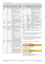


10.1.1 Order option with external actual value potentiometer, code S01
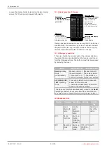
Connection X2
1
5
4
3
2
5-pin M12 built-in socket. A-coded
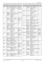
Pin
Signal name
1
UP+, output potentiometer supply voltage (+)
2
UP, input potentiometer wiper voltage
3
UP-, output potentiometer supply voltage (-)
4
n.c.
5
n.c.
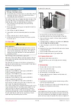
10.2 Electrical connection with cable bushing
Note: On the version with an external actual value potentiometer (code S01), a connector is always attached at connection X2.
Connection X1/X3:
M16 cable gland
Recommended cable diameter:
EX-protected version (blue cable gland: 7–9 mm
Non-EX-protected version (black cable gland: 4–10 mm
Wire cross-section
: 0.5–2.5 mm² / AWG 20 to 12
IW AO
DI DO
Terminal
Terminal label
Terminal name
Signal name
1
IW+
Iw+
Iw+, set value input (4–20 mA cur-
rent loop)/opt. HART
2
IW-
Iw-
Iw-, set value input (4–20 mA current
loop)/opt. HART
3
AO+
Iout+
Iout+, actual value output (4–20 mA/
no internal supply; passive)
4
AO-
Iout-
Iout-, actual value output (4–20 mA/
no internal supply; passive)
5
DI+
DigIn +
Digital input
6
DI-
DigIn
GND, digital input
7
DO+
Digital output
8
DO-
DigOut-
GND, digital output
www.gemu-group.com
20 / 33
GEMÜ 1441 cPos-X
10 Electrical connection


