User’s & Technical Manual –
ANALOG LIQUID LEVEL SENSOR ALLS6000
GELEC
Industrial Electronics
PAGE
19
11.
LEVEL CALIBRATION PROCEDURE
With this procedure you can calibrate the device to store the required parameters, in order
to function according to the needs of your application. For each level calibration follow the
appropriate steps. The calibration can be done either with the on-board or an external
potentiometer.
After the device installation the calibration process as described below is essential. The
correct level calibrating order is
(HL) → (LL) → (DL)
. This order is important in order to get
the optimum level measurement resolution and the on-board knob
’s 0..100
scale to
precisely correspond with the levels (LL) - (HL).
If during the calibrating process there is an idle period of 30 seconds, or the power is
interrupted, the device returns in operating mode with the pre-existed values.
(HL) High Level Calibration
•
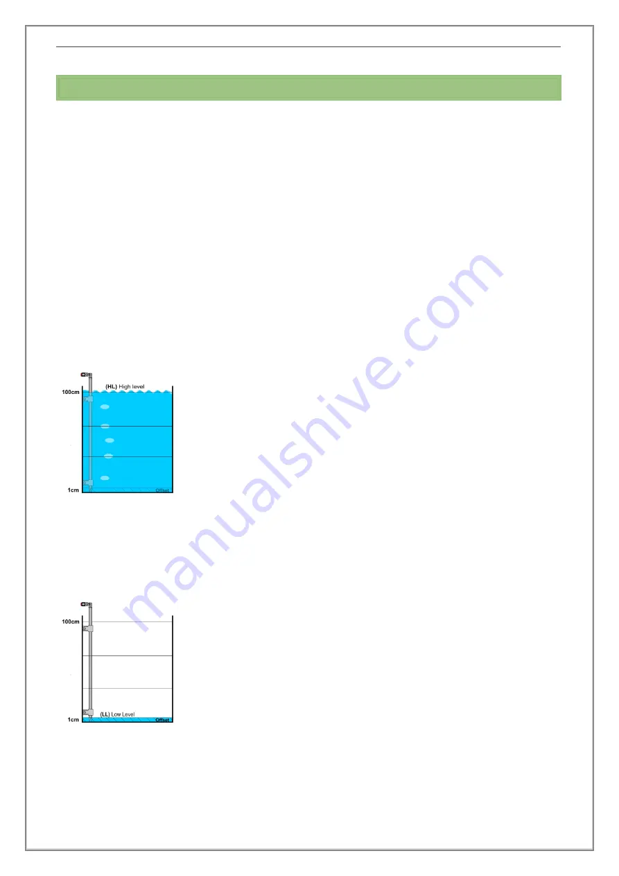
Fill the tank up to the highest desirable level. (
fig.15)
•
Press and hold the button until the led starts flashing.
•
Turn the potentiometer until you find the area where
the led flashes with green color - a clue that the value
to be registered is the High Level (HL).
•
Press and hold the button again until the led turns on
constantly.
✓
The High Level (HL) value is registered.
If the (HL) is modified through the calibration process, the (LL) and the (DL) must also be
modified.
(LL) Low Level Calibration
•
Drain the tank down to the minimum desirable level
(fig.16)
•
Press and hold the button until the led starts flashing.
•
Turn the potentiometer until you find the area where
the led flashes with red color - a clue that the value
to be registered is the Low Level (LL).
•
Press and hold the button again until the led turns on
constantly.
✓
The Low Level (LL) value is registered.
If the (LL) is modified with the calibration process, it is essential for the (DL) also to be
modified to the desirable level.
fig. 15
fig. 16


